
Description
3. Key Technical Specifications
Counter Performance Specifications
| Parameter | Value | |
|---|---|---|
| Maximum Count Rate | 80 kHz (Classic Mode) / Up to 1 MHz (Enhanced Mode in RX3i) | |
| Minimum Count Rate | 20 Hz | |
| Counter Types | Up, Down, Bi-directional (Quadrature), Difference Between Two Values | |
| Counter Configurations | 1 complex counter, 2 identical complex counters, or 4 independent simple counters | |
| Counter Resolution | 32-bit (4,294,967,295 counts) | |
| Input Filters | High Frequency: 2.5 μs | Low Frequency: 12.5 ms |
GE IC693APU300
Input Specifications
| Parameter | Value |
|---|---|
| Number of Inputs | 12 positive logic source inputs |
| Input Voltage Range | 5 VDC or 10-30 VDC |
| Input Type | Positive Logic |
| Off-State Leakage Current | 10 μA per point |
| Input Switching Frequency | Up to 8 kHz |
| Input Configuration | Count signals, direction, disable, edge-sensitive strobe, preload inputs |
Output Specifications
| Parameter | Value | |
|---|---|---|
| Number of Outputs | 4 positive logic source outputs | |
| Output Voltage Range | 4.75-6 VDC @ 20 mA maximum | 10-30 VDC @ 500 mA maximum |
| Output Type | Positive Logic | |
| Output Protection | 3 Amp Fuse for all points | |
| CMOS Load Drive Capability | Yes | |
| Output Presets | 2 preset points (On and Off) per counter |
General Specifications
| Parameter | Value |
|---|---|
| Power Consumption | 250 mA from +5 VDC backplane |
| Isolation | 250 VAC continuous (field to backplane) |
| Operating Temperature | 0°C to +60°C |
| LED Indicators | BOARD OK, CONFIG OK |
| Compatible CPU Versions | CPU350 and above required for full functionality |
| Dimensions | 13.5 cm x 13 cm x 3.6 cm |
GE IC693APU300
4. Product Introduction
The IC693APU300 is a dedicated high-speed counter module for Series 90-30 PLC systems, designed to handle pulse input rates that exceed standard PLC input capabilities or where significant PLC processing resources would be required. Unlike standard software-based counting, this module processes pulse signals directly at the hardware level, eliminating CPU scan cycle delays and ensuring accurate pulse capture even at high frequencies.
The module supports multiple counting configurations and can be set up for up, down, bi-directional (quadrature encoder) counting, or differential counting between two signals. With 12 configurable inputs and 4 outputs, it provides flexible signal processing for various industrial applications including encoder feedback for motion control, flow meter totalizing, velocity measurement, and material handling counting operations.
Key capabilities include windowing features that define valid counter accumulator ranges for strobe recognition, rollover detection flags, and support for strobe registers that capture accumulator values at specific transition events. When used in RX3i systems, enhanced mode features include support for up to 1 MHz input frequencies, 32-bit counters, Z input events, and field firmware upgrades through the backplane.
5. QA & Testing SOP
-
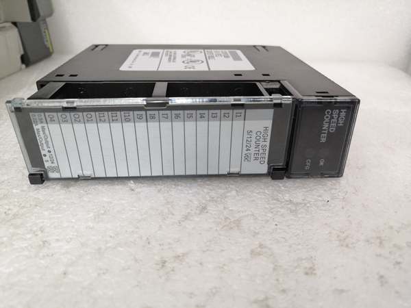
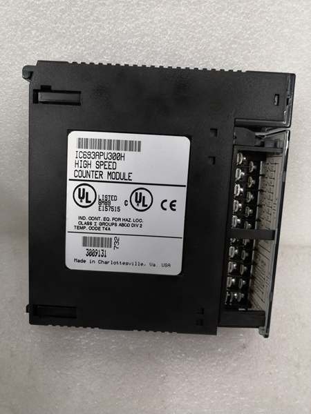
Incoming Inspection: Verify part number, revision letter, and physical condition against OEM specifications. Check for counterfeit indicators and verify that the removable terminal board (20-screw connector) is intact with no bent pins. Confirm LED indicators (BOARD OK, CONFIG OK) are present and functional.
-
Functional Testing: Install in Series 90-30 test rack with CPU350 or higher. Configure using Logicmaster 90-30/20 or VersaPro software for 4 independent simple counters. Apply pulse signals from a calibrated signal generator at 10 kHz, 50 kHz, and 80 kHz to input channels; verify %I registers accurately reflect count values within ±1 pulse tolerance. Test output response by setting preset values and confirming output activation at 10-30 VDC with 500 mA load.
-
High-Speed Performance Test: Using an oscilloscope, verify input filter response times meet 2.5 μs (high-frequency) and 12.5 ms (low-frequency) specifications. Test quadrature encoder input with A/B phase signals at 80 kHz; verify accurate directional counting without pulse loss. Measure response delay between input pulse and counter value update—should be <10 μs (hardware-level, independent of CPU scan cycle).
-
Compatibility Testing: Verify operation in both Classic and Enhanced modes when installed in RX3i chassis. Test firmware upgrade capability through RX3i CPU backplane communication (Enhanced mode). Confirm proper operation with different CPU firmware versions and verify parameter validation compatibility with redesigned module versions (IC693APU300-MA).
-
Final QC & Packaging: Perform 24-hour burn-in test at maximum count rate under full load. Verify power consumption does not exceed 250 mA @ 5 VDC. Document final test results including count accuracy, output response times, and LED status. Package in anti-static material with terminal block cover and include configuration documentation.
6. Installation Pitfalls & Guide
❗ CPU Version Compatibility RequirementsThis module requires CPU350 or higher versions for full functionality. Earlier CPU models lack necessary firmware support for high-speed counter communication. Always verify CPU model and firmware version before installation to prevent communication failures or unpredictable behavior.
❗ No Module Jumpers – Software Configuration OnlyUnlike many Series 90-30 modules, the IC693APU300 has no physical jumpers on the module itself. All configuration (counting mode, input filter settings, output presets) is performed via software. Do NOT attempt to configure input voltage ranges or counting modes through physical switches—this will result in incorrect operation.
❗ Input Signal Quality RequirementsHigh-speed counting demands clean signal integrity. The module uses built-in RC low-pass filtering (R=470Ω, C=100pF, cutoff≈3.4MHz). However, if using long cable runs (>50m) without proper shielding, signal degradation will cause counting errors. Always use twisted-pair shielded cable for encoder or sensor connections, with shield grounded within 6 inches of the module.
❗ Enhanced Mode vs Classic Mode in RX3iWhen using this module in RX3i systems, it defaults to Classic mode (80 kHz max). To access Enhanced mode features (1 MHz input, firmware upgrades), you MUST explicitly select “Enhanced mode” in Proficy Machine Edition configuration tool. Failure to select Enhanced mode will limit the module to 80 kHz operation, even though the RX3i system is capable of higher performance.
❗ Output Current LimitationOutputs provide 500 mA maximum at 10-30 VDC. If driving multiple devices or inductive loads (relays, solenoids), calculate total current draw. Exceeding 500 mA will blow the internal 3A fuse protecting all four output points. Note this fuse protects ALL outputs—if one output shorts, all outputs will be disabled until fuse is replaced.
❗ Windowing Feature ConfigurationThe windowing feature defines a valid range for counter accumulator values where strobe inputs are recognized. If strobes occur outside this window, they are ignored. Improper window configuration can cause valid process events to be missed. Always configure windowing range to encompass all expected operating values for your application.
4-Step Installation Guide:
-
Pre-Installation: Verify CPU model is CPU350 or higher with compatible firmware version. Download and install GFK-0293 High-Speed Counter User Manual. Prepare configuration using Logicmaster 90-30/20, VersaPro, or Logic Developer-PLC software. Confirm 5 VDC backplane has sufficient capacity (module draws 250 mA).
-
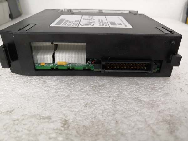
Module Installation: Power off PLC system. Insert module into any available I/O slot in Series 90-30 baseplate (single-slot design). Secure with mounting bracket. Connect removable terminal board (20-screw connector) with proper torque. Do NOT set any jumpers on module—all configuration is software-based.
-
Wiring: Connect encoder/sensor inputs to terminals I1-I12. For 5 VDC signals, use 5V OPTION terminal as reference. For 10-30 VDC signals, use 24V common reference. Connect outputs O1-O4 to load devices, observing polarity for positive logic sourcing. Use shielded cable for all input connections; ground shield within 6 inches of module terminal.
-
Configuration & Startup: Power on PLC. Verify BOARD OK and CONFIG OK LEDs illuminate solid. Load configuration software and set up counters:
- Choose configuration: 1 complex, 2 complex, or 4 simple counters
- Set counting mode: Up, Down, Bi-directional (Quadrature), or Differential
- Configure input filters: High-frequency (2.5 μs) or Low-frequency (12.5 ms)
- Set output presets (On/Off points) for each counter if using hardware outputs
- Enable windowing if applicable; define valid accumulator value range
Test with known pulse signals and verify accurate counting before full system operation.
7. FAQ
Q: What is the difference between Classic and Enhanced modes?A: Classic mode operates at 80 kHz maximum count rate and is the default in both Series 90-30 and RX3i systems. Enhanced mode, only available in RX3i systems with CPU firmware v2.60+, supports up to 1 MHz input frequency, 2 MHz internal oscillator, 32-bit counters, Z input events, and firmware upgrades over the backplane. Enhanced mode must be explicitly selected in configuration software.
Q: Can I mix different counter modes on the same module?A: It depends on the configuration selected. If configured for 4 independent simple counters, each can operate in up or down mode independently. If configured as 1 or 2 complex counters, all inputs associated with that counter must operate in the same mode (e.g., all bi-directional quadrature). You cannot have Counter 1 in up mode and Counter 2 in quadrature mode in a single complex counter configuration.
Q: Why does the module have 12 inputs but only 4 counters?A: The 12 inputs serve multiple purposes per counter: count signals (A, B, Z for quadrature), direction control, disable signals, edge-sensitive strobe inputs, and preload triggers. A single complex counter may use up to 6 inputs (A, B, Z, Direction, Disable, Strobe) plus output control. This flexible input assignment allows sophisticated counting schemes beyond simple pulse counting.
Q: Can this module replace software-based high-speed inputs?A: Yes, and it should. Software-based counting relies on CPU scan cycles (typically 20-50 ms), which cannot accurately capture pulses above a few hundred Hz. The IC693APU300 processes pulses at hardware level with <10 μs response delay, independent of CPU scan time. For encoder feedback, flow metering, or any application above ~500 Hz, hardware counting is mandatory for accuracy.
Q: What happens when the counter overflows (reaches 4,294,967,295)?A: The 32-bit counter rolls over to zero and continues counting. Rollover detection flags can be configured to trigger an output or set a status bit when overflow occurs. For applications requiring counting beyond 32-bit range, implement software logic in the PLC to track overflows and extend effective counter resolution.
Q: Can I use this module with a 5 VDC quadrature encoder?A: Yes. The module supports 5 VDC inputs directly. For quadrature encoder applications, connect A and B phases to count inputs, Z phase (index pulse) if available, and ensure proper grounding using the 5V OPTION terminal. Configure the counter for bi-directional (quadrature) mode in software.
Q: How do I troubleshoot inaccurate counting?A: Common causes include: 1) Signal quality issues—check cable length and shielding; 2) Incorrect filter setting—use high-frequency (2.5 μs) for >1 kHz signals; 3) CPU version incompatibility—verify CPU350 or higher; 4) Windowing misconfiguration—ensure strobe window covers operating range; 5) Classic mode vs Enhanced mode—in RX3i, enable Enhanced mode for high-frequency applications.
Q: Is this module compatible with PACSystems RX3i systems?A: Yes, the IC693APU300 is supported in RX3i systems. However, for new RX3i installations, the native IC694APU300 is recommended. The IC693APU300 will operate in RX3i chassis but requires RX3i CPU firmware v2.60+ for enhanced mode features. Classic mode (80 kHz) works with any RX3i CPU version.
Q: What is the input response time?A: The hardware-level input response time is <10 μs, independent of PLC scan cycle. This includes the input filter delay (2.5 μs for high-frequency mode) and counter register update time. This response enables accurate counting at 80 kHz and beyond, which is impossible with software-based counting that is tied to scan cycles.
Q: Can I replace the internal 3A output fuse?A: Yes, but it requires opening the module. The fuse protects all 4 output points from overload. Refer to GFK-0293 user manual for fuse location and replacement procedure. Note that opening the module may void warranty if performed by unauthorized personnel. For professional repair, return to authorized service center.


