
Description
Hard-Numbers: Technical Specifications
- Input Channels: 4 differential analog inputs
- Output Channels: 2 single-ended analog outputs
- Input Ranges: 0-20 mA, 4-20 mA, 4-20 mA Enhanced, 0-10V (unipolar), ±10V (bipolar)
- Output Ranges: 0-20 mA, 4-20 mA, 0-10V (unipolar), ±10V (bipolar)
- Resolution – Current Input: 5 μA per LSB (1 LSB = 5 μA)
- Resolution – Voltage Input: 2.5 mV per LSB (0-10V), 5 mV per LSB (±10V)
- Resolution – Current Output: 0.5 μA per LSB (4-20 mA), 0.6 μA per LSB (0-20 mA)
- Resolution – Voltage Output: 0.3125 mV per LSB (all voltage ranges)
- Update Rate: 3 milliseconds for all channels (combined input/output)
- Accuracy (Inputs): ±0.25% full scale @25°C, typical; ±0.5% full scale over temperature range
- Accuracy (Outputs): ±0.1% full scale @25°C, typical; ±0.25% full scale @25°C, maximum; ±0.5% full scale over temperature range
- Input Impedance – Current Mode: 250 ohms
- Input Impedance – Voltage Mode: 800 kilohms typical
- Output Load – Current Mode: Maximum 1350 ohms @ 24V supply
- Output Load – Voltage Mode: 5 mA maximum (2 kilohms minimum resistance)
- Common Mode Voltage: 200 VDC maximum
- Common Mode Rejection: >70 dB at DC; >70 dB at 60 Hz
- Cross-Channel Rejection: >70 dB from DC to 1 kHz
- Input Filter Response: 38 Hz (-3dB)
- Isolation: 250 VAC continuous; 1500 VAC for 1 minute (field to backplane)
- Power Consumption: 95 mA from internal +5VDC supply; 150 mA from external +24VDC supply
- External Supply Voltage: 20-30 VDC (24 VDC nominal, 10% ripple maximum)
- Operating Temperature: 0°C to +60°C (32°F to 140°F)
- Storage Temperature: -40°C to +85°C (-40°F to +185°F)
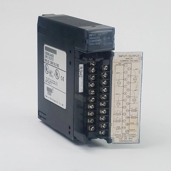
- Terminal Type: Removable 20-terminal connector block

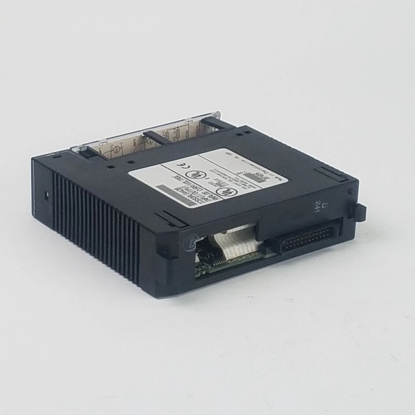
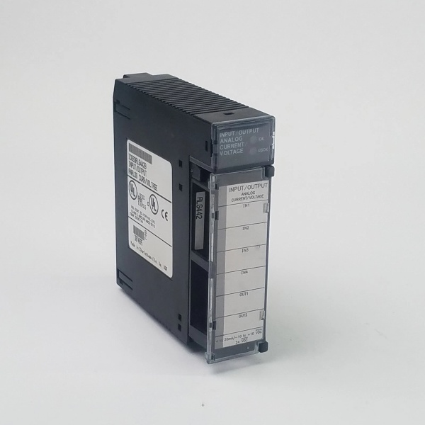
IC693ALG442
The Real-World Problem It Solves
Combination I/O modules save rack space and reduce wiring complexity by integrating inputs and outputs in a single slot. The IC693ALG442 provides four differential inputs for sensor monitoring and two single-ended outputs for actuator control, supporting both current and voltage signals without requiring separate modules. Without this combination approach, you waste rack slots and increase installation time with multiple dedicated I/O modules.
Where you’ll typically find it:
- Compact control panels: Small machinery and equipment panels where rack space is at a premium, combining temperature/pressure sensor inputs with valve positioner outputs
- Skid-mounted systems: Process skids requiring local sensor feedback and actuator control without full-scale I/O racks
- Building automation: HVAC zone controllers combining temperature sensor inputs with damper/valve analog outputs
Bottom line: The IC693ALG442 consolidates analog input and output functionality into a single module, saving rack space and simplifying wiring in space-constrained applications.
Hardware Architecture & Under-the-Hood Logic
The IC693ALG442 is a combination analog I/O module with four independent differential input channels and two single-ended output channels. It uses separate signal paths for inputs and outputs, with individual range configuration per channel via software. The module includes optical isolation between field wiring and PLC backplane, with an external +24VDC supply powering the output circuitry.
-
Input Signal Path
- Differential input amplifier rejects common-mode noise up to 200V
- Input impedance 250 ohms (current mode) or 800 kilohms (voltage mode)
- 38 Hz low-pass filter removes high-frequency noise
- 12-bit successive-approximation ADC converts each channel sequentially
-
Output Signal Path
- Single-ended output stage drives current or voltage signals to field devices
- Current outputs use a current source with compliance voltage of VUSER – 3V minimum
- Voltage outputs use a voltage source with 5 mA maximum drive capability
- Output ramp mode allows controlled transitions over 1 ms to 32 seconds
-
Range Configuration
- Software-configurable ranges per channel via Machine Edition
- Input ranges: 0-20 mA, 4-20 mA, 4-20 mA Enhanced, 0-10V, ±10V
- Output ranges: 0-20 mA, 4-20 mA, 0-10V, ±10V
- Configuration data stored in module non-volatile memory
-
Diagnostic Features
- Open-wire detection for current output modes
- High and low alarm limits configurable for all input channels
- Module health status reported to CPU via status bits
- User supply LED indicates external 24VDC is within specifications
-
Optical Isolation Barrier
- Optical couplers transmit digital data across isolation barrier
- Separate power domains for field side (+24VDC) and logic side (+5VDC)
- 1500 VAC isolation rating prevents ground loops
- Isolation protects PLC backplane from field transients
-
Power Distribution
- +5VDC from backplane powers logic side and input circuitry
- External +24VDC powers output stage and field-side electronics
- Total consumption: 95 mA @ 5VDC, 150 mA @ 24VDC
- User supply must provide current for outputs plus 150 mA module overhead
IC693ALG442
Field Service Pitfalls: What Rookies Get Wrong
Mixing input and output channel configurations
Rookies configure channel 1 as 4-20mA input and channel 2 as 4-20mA output but forget to update the PLC addressing. The %AI and %AQ reference tables get scrambled, and the wrong data goes to the wrong places.
- Field Rule: Document your channel configuration in the PLC program comments and as-built drawings. Inputs map to %AI registers, outputs map to %AQ registers—never mix them up. Verify with a loop calibrator before commissioning.
Not providing external +24VDC for outputs
Rookies power the module from the backplane +5VDC only and wonder why the outputs don’t work. The output stage requires external +24VDC for current loop driving—the backplane doesn’t supply enough power.
- Field Rule: The IC693ALG442 requires both +5VDC from the backplane AND external +24VDC for the outputs. Check the USER SUPPLY LED—if it’s off, your 24VDC is missing or out of range (20-30VDC required).
Exceeding output load limits
Rookies try to drive a 2000 ohm load with the 4-20mA output. At 20 mA, the compliance voltage requirement exceeds the module’s rating, and the output clips at 16-18 mA, causing control loop instability.
- Field Rule: Calculate your load resistance before wiring. For 4-20mA outputs, maximum load is 1350 ohms @ 24V supply. If you need more drive, add an external repeater power supply or use a dedicated output module with higher compliance.
Forgetting input impedance differences
Rookies wire a 0-10V voltage transmitter to an input configured for 0-20mA current mode. The 250-ohm input impedance loads the voltage source, causing measurement errors and potentially damaging the transmitter.
- Field Rule: Verify input range matches your transmitter type before powering up. Current mode uses 250 ohm impedance; voltage mode uses 800 kilohms. If you see readings 25% low and the transmitter is sourcing voltage, you’re in the wrong mode.
Leaving unused output channels unconnected
Rookies leave unused output channels open. The floating outputs pick up noise and drift to random values, and if configured for current mode, the open-wire fault triggers constant alarms.
- Field Rule: Short unused current outputs together with a jumper wire. For unused voltage outputs, tie them to the negative terminal or ground reference. This prevents floating outputs from generating false alarms.
Ignoring ramp mode settings
Rookies configure ramp mode for a valve output but set the ramp time to 32 seconds. The valve takes half a minute to move from closed to open, and the process overshoots its setpoint by miles.
- Field Rule: Ramp mode is for controlled transitions, not sluggish response. Set ramp time based on your actuator speed and process dynamics—typically 1-5 seconds for valve positioners. If you need instant response, disable ramp mode entirely.
Running input and output cables together
Rookies route sensor input cables and actuator output cables in the same conduit. The output switching noise couples into the sensitive differential inputs, causing jittery readings.
- Field Rule: Keep input and output cables separated by at least 6 inches. Inputs carry millivolt signals; outputs carry switching noise. If you must share a conduit, use shielded twisted-pair for inputs and ground shields at one end only.
Not verifying common-mode voltage on differential inputs
Rookies install the module with sensor grounds floating 150V above PLC ground. The 200V common-mode rating is exceeded, causing erratic readings and potential input damage.
- Field Rule: Measure ground potential difference between field devices and PLC before installation. If common-mode voltage exceeds 100V, use signal isolators on the inputs. The 200V rating is absolute maximum—keep it under 100V for reliable operation.
Commercial Availability & Pricing Note
Please note: The listed price is for reference only and is not binding. Final pricing and terms are subject to negotiation based on current market conditions and availability.


