
Description
3. Key Technical Specifications
Analog Input Specifications
| Parameter | Value |
|---|---|
| Input Channels | 4 differential |
| Current Input Ranges | 0-20mA, 4-20mA, 4-20mA Enhanced |
| Voltage Input Ranges | 0-10V unipolar, -10V to +10V bipolar |
| Resolution | 5µA (all current ranges), 2.5mV (0-10V), 5mV (-10V to +10V) |
| Absolute Accuracy | ±0.25% FS @ 25°C, ±0.5% FS over operating temp range |
| Common Mode Rejection | >70 dB at DC and 60Hz |
| Update Rate | 8ms (all channels) |
| Input Impedance | 250Ω (current), 800kΩ (voltage) |
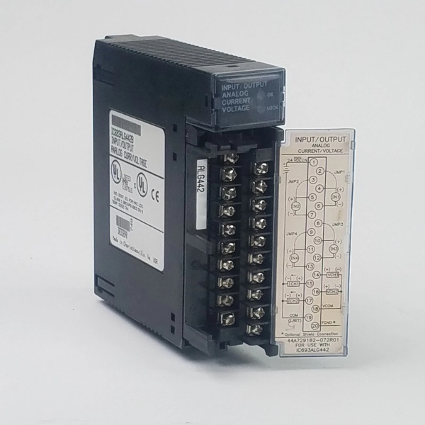
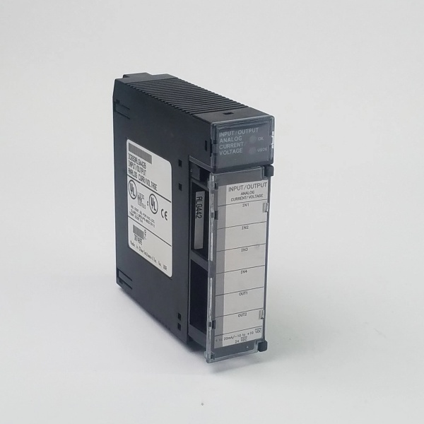
GE IC693ALG442
Analog Output Specifications
| Parameter | Value |
|---|---|
| Output Channels | 2 single-ended |
| Current Output Ranges | 0-20mA, 4-20mA |
| Voltage Output Ranges | 0-10V unipolar, -10V to +10V bipolar |
| Resolution | 0.5µA/LSB (4-20mA), 0.625µA/LSB (0-20mA), 0.3125mV/LSB (voltage) |
| Absolute Accuracy | ±0.1% FS typical @ 25°C, ±0.25% FS maximum @ 25°C |
| Update Rate | 4ms (all channels) |
| Maximum Compliance Voltage | VUSER –3V to VUSER |
| User Load (Current Mode) | 0-1350Ω at VUSER = 30V |
General Specifications
| Parameter | Value |
|---|---|
| Isolation | 250VAC continuous (field to backplane); 1500VAC for 1min |
| Power Consumption | 95mA from +5VDC backplane; 129mA from +24VDC user supply |
| External Supply | 20-30VDC (10% ripple max) |
| Operating Temperature | -40°C to +70°C |
| Module Dimensions | 3.6cm x 13cm x 13.5cm |
4. Product Introduction
This combination analog I/O module provides 4 differential input channels and 2 single-ended output channels for Series 90-30 PLC systems, eliminating the need for separate input and output modules. Each channel can be individually configured for multiple current and voltage ranges through software, with optional enhanced input ranges for 4-20mA signals.
The unit supports ramp mode operation, where output channels transition to new values over time rather than immediately, and can be configured to hold last state or reset to low end of range upon power interruption. It also provides comprehensive diagnostics including input alarms, open-wire fault detection for outputs, and module health status reporting.

GE IC693ALG442
5. QA & Testing SOP
-
Incoming Inspection: Verify part number and revision against OEM datasheets. Check for counterfeit markings, bent pins, or thermal damage. Document terminal block pin assignments and LED status indicators before testing begins. Ensure proper jumper setting for enhanced 4-20mA input mode if required.
-
Live Testing: Power up in a Series 90-30 test rack with +5VDC backplane power and +24VDC external supply connected. Write known values to %AQ registers and measure output current at IOUTx terminals using a calibrated Fluke 773 milliamp clamp meter and precision resistor. Inject test signals to input channels and verify %AI register values match expected measurements. Operate under full load for 24 hours to confirm stability.
-
Electrical Testing: Verify isolation resistance exceeds 10MΩ between field side and backplane (measured at 500VDC). Test power supply switching by applying 24VDC external supply; confirm the module switches from backplane to user power when external voltage >21.5V. Measure common mode rejection to ensure it meets >70dB specifications.
-
Firmware/Config Backup: Record firmware version and take photos of configuration parameters stored in flash memory. Document ramp mode configuration capabilities and alarm limit settings. Verify the unit supports both Hand-Held Programmer and software-based configuration.
-
Final QC & Packaging: The module passes final visual inspection before being tagged with QC documentation showing measured values at key test points. It ships in anti-static packaging with original terminal block connector included, along with jumper configuration instructions for enhanced input modes.
6. Installation Pitfalls & Guide
❗ Jumper Configuration for Enhanced Input ModeThis unit requires a jumper setting for selecting enhanced 4-20mA input mode. Failing to set this jumper when using enhanced range will result in incorrect readings. The jumper is typically located near the terminal block on the module circuit board. Consult the wiring diagram for exact location.
❗ Differential Input Wiring RequirementsInput channels are differential only. Do NOT wire them as single-ended inputs, as this will cause measurement errors and potentially damage the module. Ensure proper polarity and use twisted-shielded cable to maintain common mode rejection specifications.
❗ CPU Firmware CompatibilityFor CPU firmware versions 3.3 to 4.6, you may need to configure specific memory allocation settings. Refer to OEM documentation for exact requirements, as mismatch can cause module communication failures or data corruption.
❗ Ramp Mode Configuration ComplexityRamp mode operation requires specific programming using COMMREQ instructions in your PLC program. An incorrect sample code exists in some versions of GFK-0898F documentation. Use verified sample code or consult technical support when implementing ramp mode.
4-Step Installation Guide:
-
Pre-Wiring: Verify jumper setting for enhanced input mode matches application requirements. Connect external 24VDC to terminals corresponding to 24VIN and user supply return. Connect shield ground to appropriate terminal to maintain common mode rejection.
-
Configuration: Use Logicmaster 90-30 v5.0+, CIMPLICITY Control v2.0+, or Hand-Held Programmer to configure channel ranges, alarm limits, and stop mode behavior. Set output channels to ramp mode if required for your application.
-
Wiring: Wire field devices to input channels using differential wiring configuration. Connect output devices to voltage (OUTx) or current (IOUTx) terminals as configured. Use terminal block labels corresponding to your signal types and ranges.
-
Power-on Test: Power up, check OK/USOK LEDs (both ON = normal). Inject test signals to input channels and verify %AI register values match expected measurements. Write values to %AQ registers and confirm output signals meet specifications. Test ramp mode operation if configured.
7. FAQ
Q: What is the enhanced 4-20mA input mode?A: The enhanced mode provides better noise rejection and accuracy for 4-20mA signals by using a different scaling method that extends effective resolution. This mode is selected via a jumper on the module and provides more precise measurement of low-level current signals.
Q: Can input and output channels be configured independently?A: Yes, each input channel can be individually configured for different ranges (current or voltage), and each output channel can be independently set to different current or voltage ranges based on application requirements.
Q: What is ramp mode and why would I use it?A: Ramp mode causes the output channel to transition to a new value over a programmable period of time rather than changing immediately. This is useful for applications where sudden changes could cause process instability, such as valve positioning or motor speed control.
Q: Does this module support firmware upgrades?A: Yes, when installed in RX3i racks, this module supports firmware upgrades in the field. Series 90-30 installations may require module replacement for firmware updates, depending on revision.
Q: What happens if I exceed the specified input range?A: The module will clip values outside the specified range to the nearest valid value before converting to digital. Overvoltage or overcurrent beyond specified limits may damage the module or reduce its lifespan.
Q: Can I install this module in a PACSystems RX3i system?A: Yes, this module is supported in both Series 90-30 and RX3i systems. For new RX3i installations, the native RX3i module IC694ALG442 is recommended, but IC693ALG442 will operate in an RX3i chassis.
Q: How many IC693ALG442 modules can be installed in a single rack?A: The number is limited by:
- Power supply capacity (each module requires 129mA @ +24VDC)
- CPU’s analog data handling capability (max 512 analog I/O points for most Series 90-30 CPUs)
- Available I/O slots in the rack
Q: What is the maximum cable length for input connections?A: Recommended maximum cable length is 500 feet (150 meters) for 22AWG twisted-shielded cable. Longer runs may require signal conditioning due to potential signal degradation and increased noise susceptibility.


