
Description
3. Key Technical Specifications
| Parameter | Value |
|---|---|
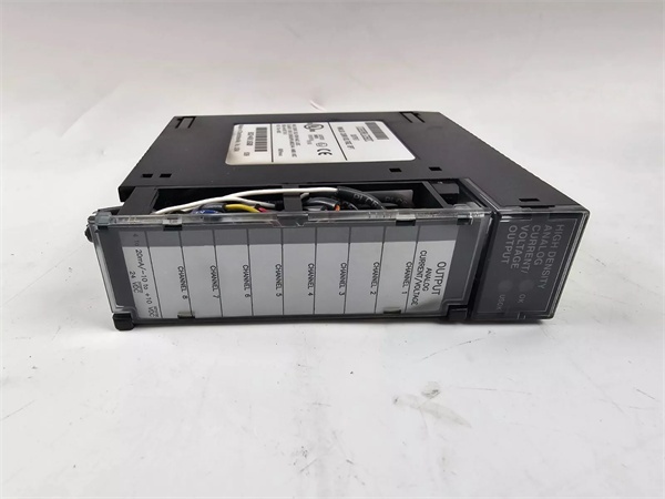
| Output Channels | 8 single-ended, individually configurable |
| Current Ranges | 4-20mA, 0-20mA |
| Voltage Ranges | 0-10V unipolar, -10V to +10V bipolar |
| Resolution | 0.5µA/LSB (4-20mA), 0.625µA/LSB (0-20mA), 0.3125mV/LSB (voltage) |
| Absolute Accuracy | ±0.1% FS (current), ±0.25% FS (voltage) @ 25°C |
| Update Rate | 8ms (all 8 channels) |
| Isolation | 250VAC continuous (field to backplane); 1500VDC for 1min |
| Power Consumption | 110mA from +5VDC backplane; 315mA from +24VDC user supply |
| External Supply | 20-30VDC (10% ripple max) |
| User Load (Current) | 0-850Ω (20V supply) to 1350Ω (30V supply) |
| Output Load (Voltage) | 5mA max, 2kΩ min resistance |
IC693ALG392
4. Product Introduction
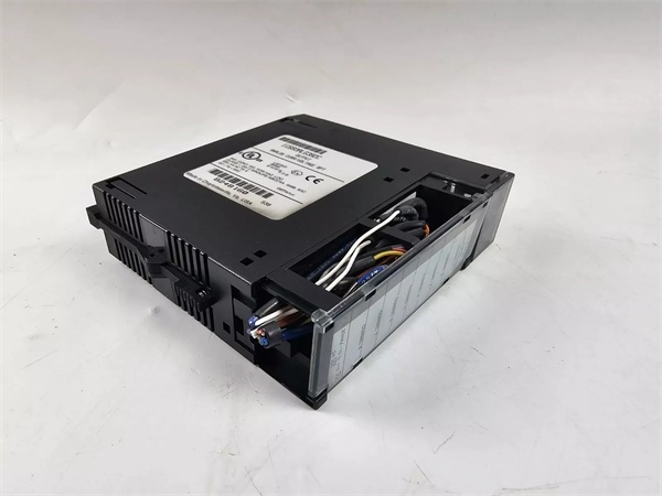
The module is an 8-channel analog output unit designed for Series 90-30 PLC systems, converting digital controller signals to precision industrial current or voltage outputs. Each channel is independently software-configurable for multiple ranges without requiring hardware adjustments.
This unit features updated processor and D/A converter technology for improved signal quality and reliability, while removing compatibility with the Series 90-30 Hand-held Programmer. It provides isolated field-side connections and supports open-wire fault detection in current mode.
5. QA & Testing SOP
- Incoming Inspection: Verify part number and revision against OEM datasheets. Trace lot codes to confirm manufacturing origin. Check for counterfeit markings, bent pins, or thermal damage using a high-resolution camera for documentation.
- Live Testing: Power up in a Series 90-30 test rack with +5VDC backplane power and +24VDC external supply connected. Write known values to %AQ registers and measure output current using a calibrated Fluke 773 milliamp clamp meter and precision resistor. Operate under full load (20mA per channel) for 24 hours to confirm stability.
- Electrical Testing: Verify isolation resistance exceeds 10MΩ between field side and backplane (measured at 500VDC). Test power supply switching by applying 24VDC external supply; confirm module switches from backplane to user power when external voltage >21.5V.
- Firmware/Config Backup: Record firmware version 1.00 (BD revision) and take photos of configuration parameters stored in flash memory. Note that this unit does not support hand-held programmer configuration.
- Final QC & Packaging: Module passes final visual inspection before being tagged with QC documentation showing measured values at key test points. It ships in anti-static packaging with original terminal block connector included.
6. Installation Pitfalls & Guide
❗ Hand-held Programmer Compatibility LossThis unit does NOT support the Series 90-30 Hand-held Programmer. Attempting configuration with older tools will fail and may cause communication errors. Use Logicmaster 90-30 v5.0+ or CIMPLICITY Control v2.0+ software only.
❗ CPU Firmware MismatchFor CPU firmware versions 3.3 to 4.6, configure for 16 %I inputs or a Loss of Module Fault will occur. CPU firmware v5.0+ supports 8/16 %I inputs. Failing to set this correctly during configuration results in module communication failures.
❗ Insufficient External PowerThe device requires a user-supplied 20-30VDC external power source connected directly to the terminal block. Backplane +24VDC is insufficient for analog output power. Ensure external supply provides at least 315mA @ +24VDC.
❗ RF Interference SusceptibilityIn high-RF environments, accuracy may degrade to ±1% FS (current) and ±3% FS (voltage). The unit must be mounted in a metal enclosure to meet IEC 61000-6-2 EMC requirements.
4-Step Replacement Guide:
- Pre-install: Document existing module configuration, take photos of wiring, and verify replacement unit revision. Calculate total power requirements to ensure power supply headroom exists.
- Removal: Disconnect external power and backplane connections. Label field wiring to match terminal numbers for easy reconnection.
- Install: Mount replacement unit in same I/O slot. Reconnect field wiring using documented labels. Connect external 24VDC power to terminals 1 (24VIN) and 19 (I COM).
- Power-on Test: Power up, check OK/USOK LEDs (both ON = normal). Inject test values to confirm output accuracy matches OEM specifications.

IC693ALG392
7. FAQ
Q: Why was hand-held programmer support removed?A: The OEM removed support to focus on software-based configuration tools offering more advanced features and better long-term support. This change also enabled use of newer processor technology incompatible with older hand-held hardware interfaces.
Q: Can I use existing programs with this unit?A: Yes. While you cannot configure the module with a hand-held programmer, existing programs configured with this method on older modules will still run. Register mapping and data formats remain compatible.
Q: What firmware version does this unit use?A: The module ships with firmware version 1.00. Note that this revision cannot be upgraded to firmware 1.60, which is only available for later CF revision modules. Firmware upgrades are not field-serviceable.
Q: Is the module compatible with RX3i systems?A: Yes, it works with Series 90-30 and RX3i systems. However, constant sweep mode may cause over-sweep faults in RX3i setups. Verify with OEM datasheet for specific system compatibility matrix.
Q: What happens if power is interrupted?A: If system power is lost but external user power remains, outputs maintain last value or reset to zero as configured via software. If external power is also lost, all outputs reset to zero.
Q: Can this unit be used as a replacement for IC693ALG392-B?A: Yes, with two key considerations: (1) Configuration must now be done via software instead of hand-held programmer, and (2) The updated processor may have slightly different signal characteristics but maintains functional compatibility.
Q: How many units can be installed in a single rack?A: There is no hard limit, but actual quantity is constrained by power supply capacity (315mA @ +24VDC per module) and CPU analog output capability (max 512 analog outputs for most Series 90-30 CPUs). Verify system power budget before installation.


