
Description
Hard-Numbers: Technical Specifications
- Input Channels: 2 isolated counter inputs (differential or single-ended)
- Counting Frequency: Up to 80 kHz per channel
- Counter Resolution: 32-bit signed counter (±2,147,483,647 counts)
- Input Types: Quadrature A/B, Up/Down, Pulse/Direction, Frequency Measurement
- Input Voltage: 5-24 VDC logic (sink/source compatible)
- Input Impedance: Approximately 3 kΩ
- Isolation: 1500 V RMS between field side and logic side
- Input Filter: Configurable (software selectable)
- Power Consumption: 350 mA from +5VDC backplane; 25 mA from +24VDC backplane
- Data Format: 32-bit signed count value in %I registers; latched count and frequency data in %AI registers
- Operating Temperature: 0°C to +60°C (32°F to 140°F)
- Storage Temperature: -40°C to +85°C (-40°F to +185°F)
- Humidity: 5–95% non-condensing
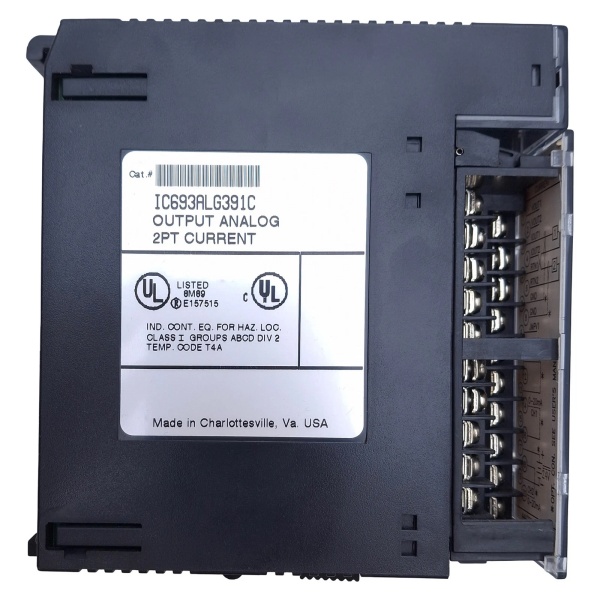
- Terminal Type: Removable 40-pin terminal block

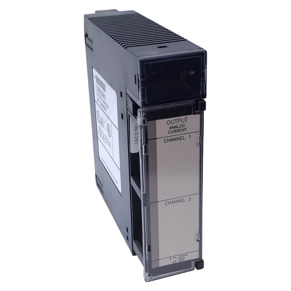
GE IC693ALG391
The Real-World Problem It Solves
Standard PLC digital inputs max out at a few hundred Hz, which is useless for encoder feedback and high-speed pulse counting. The IC693ALG391F provides two independent 80 kHz counters with quadrature decoder hardware, allowing your Series 90-30 to read position and velocity from encoders in real-time without missing pulses.
Where you’ll typically find it:
- Material handling: Reading position from rotary encoders on conveyor drives and hoist motors
- Cut-to-length machines: Measuring material length from measuring wheels and linear encoders for accurate cutting
- Web processing: Synchronizing drive speeds using encoder feedback from unwind/rewind rolls and nip rollers
Bottom line: The IC693ALG391F gives your Series 90-30 two dedicated high-speed counter channels for encoder interfaces and pulse counting beyond what standard I/O can handle.
Hardware Architecture & Under-the-Hood Logic
The IC693ALG391F is a high-speed counter module with two independent 32-bit counter channels. It uses dedicated counter hardware with quadrature decoding logic, not the PLC scan cycle, ensuring accurate pulse counting at speeds up to 80 kHz. The module includes optical isolation and configurable input filtering.
-
Input Conditioning Stage
- Differential or single-ended input buffers accept 5-24 VDC signals
- Configurable input filter (software selectable) rejects bounce and noise
- Input protection clamps transients to ±30V
- Schmitt trigger conditioning ensures clean digital edges
-
Counter Hardware
- Two independent 32-bit up/down counters operate independently of PLC scan
- Quadrature decoder (A/B channels) supports 1x, 2x, and 4x resolution modes
- Hardware latching captures count values on command or external trigger
- Frequency measurement mode calculates input frequency in Hz
-
Counter Modes
- Up/Down mode: counts up on one input, down on another
- Quadrature mode: decodes A/B phase relationship for direction and count
- Pulse/Direction mode: counts pulses on one input, direction on another
- Frequency mode: measures input frequency for speed monitoring
-
Latch & Compare Functions
- Hardware latching captures current count value on external trigger or software command
- Compare registers trigger outputs when count reaches preset values
- Programmable output pulses for position or velocity-based events
- Latched values and frequency data accessible in %AI registers
-
Data Output to CPU
- Real-time count values stored in %I registers (32-bit signed)
- Latched count values and frequency data in %AI registers
- Status bits indicate direction, overflow/underflow, and alarm conditions
- CPU reads data via Series 90-30 backplane bus
GE IC693ALG391
Field Service Pitfalls: What Rookies Get Wrong
Running encoder cables near VFD outputs
Rookies route encoder cables in the same conduit as VFD motor leads. The induced noise causes false counting at high speeds, and the conveyor overshoots its 终止 position by 2-3 inches every cycle.
- Field Rule: Keep encoder cables at least 12 inches away from VFD motor leads. Use shielded twisted-pair encoder cable with foil + braid shield. Ground the shield at the encoder end only—never ground both ends.
Mixing quadrature resolution modes
You replace a failed encoder but don’t verify the quadrature mode in software. The old encoder used 4x mode, the new one uses 1x mode, and the machine now travels 4x the commanded distance before 终止ping.
- Field Rule: When replacing an encoder, verify the quadrature resolution setting (1x, 2x, or 4x) in the PLC software matches the encoder specification. A 1000 PPR encoder in 4x mode counts 4000 pulses per revolution—in 1x mode it’s only 1000.
Not compensating for input filter delay
Rookies crank the input filter to maximum to suppress noise. The filter introduces a 500 µs delay, and at 80 kHz counting speed, the module misses pulses and loses position accuracy.
- Field Rule: Set the input filter to the minimum value that provides reliable counting. Start at 10-20 µs and only increase if you see bounce or false counts. Longer filters cost you resolution at high speeds.
Ignoring common-mode voltage limits
Rookies install the module with encoder grounds floating 50V above PLC ground. The 1500V isolation handles this, but they add a ground reference at the encoder that drives common-mode current through the input protection network, causing intermittent counts.
- Field Rule: Measure the ground potential difference between encoder and PLC before installation. If it exceeds 10V, use an isolated encoder power supply or an encoder signal isolator. Don’t rely on the module’s isolation to fix bad grounding.
Leaving unused channels unconnected
Rookies leave unused counter channels disconnected. The floating inputs pick up electrical noise, causing the counter to drift randomly and triggering false position alarms.
- Field Rule: Short unused channel inputs together at the terminal block. Connect the positive and negative terminals of unused channels to each other to tie them to a defined logic state and prevent floating inputs from counting garbage.
Forgetting to latch counts before reading
Rookies read the moving count value directly from the %I register. The counter is still incrementing during the PLC scan, and the value changes between read instructions, causing the machine to hunt or oscillate around the setpoint.
- Field Rule: Use the hardware latch function to capture a stable count value. Trigger the latch via software command or external input, then read the latched value from %AI registers. The latched value won’t change until you latch again.
Powering encoders from non-isolated supplies
Rookies power the encoder from the same 24V supply that feeds VFDs and motors. The VFD switching noise couples into the encoder power rails, causing jittery pulses and missed counts at high speeds.
- Field Rule: Use an isolated DC-DC converter or a dedicated linear power supply for encoders. Keep encoder power clean and separate from motor drive power. If you must share a supply, add a pi-filter (inductor-capacitor-inductor) at the encoder power input.
Not verifying direction before commissioning
Rookies wire an encoder and power up the machine without checking direction. The machine drives backward when commanded forward, crashing into hard 终止s and damaging equipment.
- Field Rule: After wiring, jog the axis slowly in the forward direction and verify the counter is incrementing (not decrementing). If backward, swap the A and B channels or change the direction bit in software—never swap the motor leads to compensate.
Commercial Availability & Pricing Note
Please note: The listed price is for reference only and is not binding. Final pricing and terms are subject to negotiation based on current market conditions and availability.


