
Description
3. Key Technical Specifications
| Parameter | Value |
|---|---|
| Output Channels | 2 |
| Output Current Ranges | 4-20 mA, 0-20 mA |
| Output Voltage Ranges | 1-5 V, 0-5 V (via JMPVx jumper) |
| Resolution | 4 µA/bit (4-20 mA), 5 µA/bit (0-20 mA) |
| Absolute Accuracy | ±8 µA at 25°C (4-20 mA), ±10 µA at 25°C (0-20 mA) |
| Update Rate | 5 ms (both channels) |
| Maximum Compliance Voltage | 25 V |
| User Load (Current Mode) | 0-850 Ω |
| Output Load Capacitance | 2000 pF |
| Output Load Inductance | 1 H |
| Isolation | 1500 volts between field and logic side |
| Internal Power Consumption | 30 mA from +5V supply / 215 mA from Isolated +24V backplane or user supply |
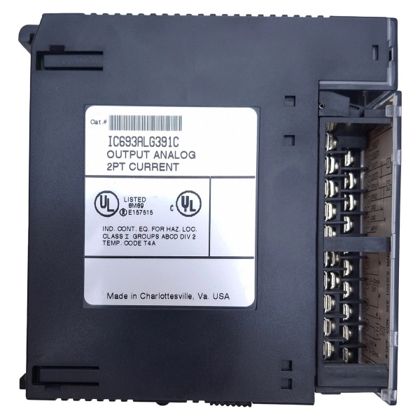
GE IC693ALG391
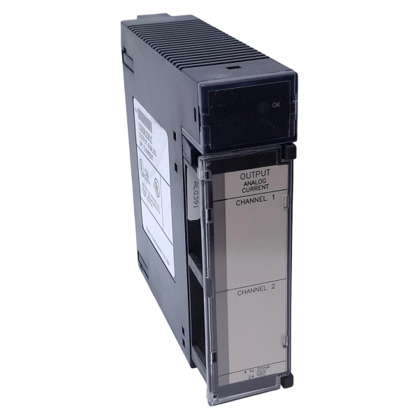
4. Product Introduction
The GE IC693ALG391 is a 2-channel analog current/voltage output module for the GE Series 90-30 PLC platform. Each channel converts 12-bit digital data to analog outputs, supporting 4-20 mA and 0-20 mA current ranges. Via JMPVx jumpers, the device can operate as a less accurate voltage source outputting 1-5 V or 0-5 V. The 1500 V optical isolation protects the backplane from field noise.
This unit features 25 V compliance voltage for driving long current loops and 850 Ω maximum load resistance. Update rate is 5 ms for both channels. A DEF0/4 jumper configures CPU STOP/RESET behavior: outputs default to 4 mA (or 0 mA) or hold last state. Range jumpers (RANGE1/RANGE2) select between 4-20 mA and 0-20 mA per channel.
5. QA & Testing SOP
Our QC process for this 2-channel analog current/voltage output module follows a rigorous 5-step verification:
1. Incoming Inspection: We verify part numbers and revision levels against GE/Emerson datasheets. Physical inspection checks for corrosion, bent pins, counterfeit markings, or thermal damage. We trace lot codes to confirm manufacturing origin. Photo documentation captures the removable terminal block configuration, including DEF0/4, RANGE1/RANGE2, and JMPV1/JMPV2 jumper positions before testing begins.
2. Live Testing: The module powers up in a Series 90-30 test rack with +5 VDC backplane power and +24 VDC external supply connected. We write known values to %AQ registers and measure output current at the IOUTx terminals using a calibrated Fluke 773 milliamp clamp meter and precision resistor. Test points include 4 mA, 12 mA, 20 mA for 4-20 mA range and 0 mA, 10 mA, 20 mA for 0-20 mA range. We test voltage mode via JMPVx jumpers using a Fluke 87V multimeter. We simulate CPU STOP and verify output behavior based on DEF0/4 jumper setting (default to 0/4 mA or hold last state). Continuous operation under full load (20 mA per channel) for 24 hours confirms stability.
3. Electrical Testing: We verify isolation resistance exceeds 10 MΩ between field side and backplane (measured at 500 VDC). Load testing confirms the device drives up to 850 Ω loads at 20 mA without voltage droop exceeding 25 V compliance limit. We verify the user-supplied power input accepts 20-30 VDC and switches over from backplane when user supply voltage exceeds 21.5-26.5 V.
4. Firmware/Config Backup: We record the exact module revision. Configuration parameters including range settings, voltage/current mode selection, and DEF0/4 jumper configuration are documented. All test data is archived with the module’s serial number for traceability.
5. Final QC & Packaging: The module passes final visual inspection, receives a QC pass tag documenting measured values at 4/12/20 mA for both ranges and voltage outputs, and ships in anti-static packaging with the original terminal block connector. Each unit includes a test report verifying resolution, accuracy, isolation, and jumper functionality.

GE IC693ALG391
6. Installation Pitfalls & Guide
❗ Exceeding 850 Ω Load Resistance
The maximum load resistance in current mode is 850 Ω. Exceeding this limit causes the output voltage to hit the 25 V compliance ceiling, resulting in inaccurate current or output saturation. Calculate total loop resistance including cable resistance. If field device resistance exceeds 850 Ω, reduce loop resistance by using larger gauge wire or installing the device closer to the module.
❗ Incorrect DEF0/4 Jumper Configuration
The DEF0/4 jumper determines output behavior on CPU STOP or RESET. With jumper installed, outputs default to 4 mA (4-20 mA range) or 0 mA (0-20 mA range). With jumper removed, outputs hold last state. Failing to document the existing jumper position before removal results in unexpected equipment behavior during CPU 终止s. Always photograph the terminal block before extraction.
❗ RANGE1/RANGE2 Jumper Confusion
RANGE1 and RANGE2 jumpers select the current range. Without jumpers installed, the default is 4-20 mA. Installing RANGE1 or RANGE2 changes the scaling to 0-20 mA. Placing the wrong jumper causes output scaling errors—your PLC sends 32000 counts expecting 20 mA, but the module outputs 0 mA (or vice versa). Verify PLC %AQ scaling matches the hardware jumper configuration per channel.
❗ Missing JMPVx Jumper for Voltage Mode
If your application requires voltage output (1-5 V or 0-5 V), you must install JMPV1 or JMPV2 jumper. Without these jumpers, the module operates in current mode and will not drive voltage into resistive loads. The voltage output is derived from the current output through internal circuitry—accuracy is lower than dedicated voltage modules. For high-precision voltage needs, use IC693ALG390.
❗ Backplane +24 V Current Headroom Depletion
This device draws 215 mA from the isolated +24 V supply in addition to output loop currents. In racks with multiple analog output modules, the PLC power supply may reach capacity limits, causing voltage sag and affecting all rack modules. Calculate total +24 V load. GE limits installation to three modules per baseplate when using only backplane power. Add an external user-supplied +24 VDC (20-30 VDC) to relieve backplane load and ensure outputs maintain state during PLC power loss.
4-Step Replacement Guide:
- Pre-install: Document the DEF0/4, RANGE1/RANGE2, and JMPV1/JMPV2 jumper positions. Photograph the terminal block wiring (which field device connects to IOUT1/IOUT2 and RTN1/RTN2). Calculate total loop resistance and verify it is under 850 Ω.
- Removal: Power down the rack and external supplies. Disconnect the field wiring. Remove the failed module and transfer the terminal block assembly to the replacement unit, maintaining all jumper positions.
- Install: Install the replacement module in the rack slot. Reconnect the terminal block. Ensure shield connections are properly terminated to GND on the terminal block.
- Power-on Test: Apply power and verify the LED illuminates. Write test values to %AQ registers and measure output currents with a calibrated clamp meter. Verify scaling matches the RANGE jumper configuration (4-20 mA vs. 0-20 mA). Test DEF0 functionality by cycling the CPU and observing output behavior (default vs. hold last state).
7. FAQ
Q: What is the difference between IC693ALG390 and IC693ALG391?
A: IC693ALG390 is a voltage-only output module (-10 to +10 VDC), while IC693ALG391 is primarily a current output module (4-20 mA, 0-20 mA) with optional voltage capability (1-5 V, 0-5 V) via JMPVx jumpers. The current module provides 25 V compliance voltage for driving long loops, whereas the voltage module is limited to 5 mA output current. Use IC693ALG391 for 4-20 mA current loops and IC693ALG390 for high-precision voltage control.
Q: Can I use an external +24 VDC power supply instead of the PLC backplane?
A: Yes, and it is recommended for installations with three or more modules. The module accepts 20-30 VDC at the IN24V and I GND terminals. When user supply voltage exceeds the backplane voltage (21.5-26.5 V), the module automatically switches to external power. This reduces backplane load and ensures outputs maintain state if PLC power fails (when Hold Last State is configured). Ensure the external supply shares a common ground reference with the backplane.
Q: What happens if I exceed the 850 Ω load resistance?
A: The output hits the 25 V compliance voltage limit and current regulation fails—the output saturates and no longer accurately reflects the %AQ register value. Field devices receive incorrect signals. Calculate total loop resistance (wire resistance + device input resistance). If resistance approaches 850 Ω, shorten cable runs, use larger gauge wire, or install a loop-powered isolator near the module.
Q: How do I configure the module for 4-20 mA vs. 0-20 mA range?
A: The default configuration (no RANGE jumpers) is 4-20 mA, where 0 counts = 4 mA and 32000 counts = 20 mA. Installing RANGE1 or RANGE2 jumper changes the scaling to 0-20 mA, where 0 counts = 0 mA and 32000 counts = 20 mA. Each channel has independent RANGE jumpers. Ensure your PLC program scaling factors match the hardware configuration—mismatch causes significant process errors.
Q: What is the DEF0/4 jumper function?
A: The DEF0/4 jumper configures output behavior on CPU STOP or RESET. With jumper installed, outputs default to 4 mA (4-20 mA range) or 0 mA (0-20 mA range)—this is a fail-safe state driving actuators to predetermined positions. With jumper removed, outputs hold their last value, maintaining current output until power is cycled. Select based on process safety requirements: fail-safe vs. hold-last-state continuity.
Q: Can I mix current and voltage outputs on the same module?
A: Yes. Each channel independently operates as current or voltage source via JMPV1 and JMPV2 jumpers. Channel 1 can output 4-20 mA current while Channel 2 outputs 1-5 V voltage simultaneously. However, voltage mode accuracy is lower (±50 mV) compared to dedicated voltage modules. Voltage output is derived from current loop through internal circuitry—use for setpoint applications where ±50 mV tolerance is acceptable.
Q: Is this module still manufactured?
A: The Series 90-30 platform is discontinued by GE/Emerson. Most available units are New Surplus or refurbished. Verify the module revision matches your existing rack configuration. Emerson acquired GE Intelligent Platforms in 2019 and continues limited support for legacy parts, but new production has ceased.
Q: Why does my output drift over time?
A: Check compliance voltage headroom. If loop resistance is close to 850 Ω, minor resistance changes from temperature or aging cause voltage saturation and current drift. Verify load resistance is comfortably under the limit. Also ensure external supply voltage is stable and within 20-30 VDC range. Excessive ripple (>10%) causes output instability.
Q: What is the maximum number of these modules per baseplate?
A: GE specifies a maximum of three IC693ALG391 modules per baseplate when powered solely from the backplane +24 V supply. Each module draws 215 mA, totaling 645 mA for three modules. This approaches the capacity of standard 30 W power supplies. Installing user-supplied external power for each module allows more than three modules by offloading the backplane. Verify your power supply capacity before exceeding three modules.


