

Description
Hard-Numbers: Technical Specifications
- Input Channels: 8 single-ended thermocouple inputs
- Thermocouple Types: J, K, T, E, R, S, B (software configurable per channel)
- Temperature Ranges: Depends on thermocouple type (typically -200°C to +1800°C depending on type)
- Resolution: 16-bit; approximately 0.1°C to 0.5°C depending on thermocouple type
- Update Rate: 240 milliseconds per channel (full scan: approximately 2 seconds for all 8 channels)
- Accuracy: ±0.5°C to ±2.5°C depending on thermocouple type and temperature range
- Cold Junction Compensation (CJC): Automatic, using internal sensor at terminal block
- Isolation: 1500 V RMS between field side and logic side
- Input Filter: 60 Hz rejection
- Power Consumption: 350 mA from +5VDC backplane
- Data Format: 16-bit signed integer in %AI registers (scaled to 0.1°C or 1°C units)
- Operating Temperature: 0°C to +60°C (32°F to 140°F)
- Storage Temperature: -40°C to +85°C (-40°F to +185°F)
- Humidity: 5–95% non-condensing
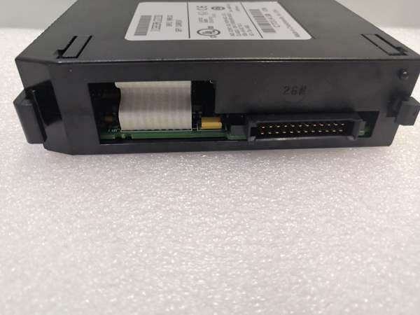
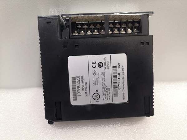
- Terminal Type: Removable 40-pin terminal block

GE IC693ALG223
The Real-World Problem It Solves
Thermocouples provide accurate temperature measurement in extreme environments, but the millivolt signals require cold junction compensation and isolation from electrical noise. The IC693ALG223-FR handles the signal conditioning, CJC, and A/D conversion for eight thermocouple inputs, rejecting noise and breaking ground loops that would otherwise corrupt temperature readings in process control applications in France.
Where you’ll typically find it:
- Chemical reactors in France: Monitoring reactor temperature profiles using multiple Type K or J thermocouples for exothermic reaction control
- Heat treatment furnaces in France: Temperature uniformity surveys and process monitoring with Type S or R thermocouples in high-temperature applications
- Food processing in France: Pasteurization and sterilization temperature monitoring using Type T thermocouples in sanitary applications
Bottom line: The IC693ALG223-FR converts fragile thermocouple millivolt signals into reliable temperature data your PLC can use for process control and safety interlocks in French industrial environments.
Hardware Architecture & Under-the-Hood Logic
The IC693ALG223-FR is an isolated thermocouple input module with eight independent input channels. It uses a 16-bit sigma-delta ADC with automatic cold junction compensation and software-configurable thermocouple type selection. The module includes an onboard microprocessor for signal processing and linearization.
-
Input Conditioning Stage
- Thermocouple inputs are galvanically isolated from the PLC backplane
- Input protection clamps transients to ±15V
- Differential input amplifier rejects common-mode noise
- Input filter provides 60 Hz rejection for industrial environments
-
Cold Junction Compensation (CJC)
- Precision temperature sensor mounted at terminal block measures ambient temperature
- CJC value is added to thermocouple millivolt reading during linearization
- Automatic compensation occurs on each scan cycle
- Requires terminal block to be installed for accurate CJC
-
A/D Conversion Stage
- 16-bit sigma-delta ADC converts thermocouple millivolt signals to digital values
- Sequential scanning of all 8 channels (240 ms per channel)
- Internal voltage reference provides conversion accuracy
- Digital filtering reduces noise on each channel
-
Linearization & Scaling
- Microprocessor applies thermocouple type linearization curves (ITS-90 standard)
- Software-configurable thermocouple types per channel
- Scaled temperature values stored in %AI registers
- Configurable engineering units (°C or °F)
-
Optical Isolation Barrier
- Optical couplers transmit digital data across 1500V RMS isolation barrier
- Separate power domains for field side and logic side
- Prevents ground loop currents from affecting measurements
- Isolated reference voltage ensures accuracy
GE IC693ALG223
Field Service Pitfalls: What Rookies Get Wrong
Mixing thermocouple types
Rookies wire a Type K thermocouple to a channel configured for Type J. The linearization is wrong by 40-50%, causing temperature readings to be significantly off and potentially triggering false alarms or unsafe process conditions.
- Field Rule: Label each thermocouple lead at the sensor and at the module with its type (color-coded: Type J=Black/White, Type K=Yellow/Red). Verify thermocouple type configuration in PLC software matches the physical sensor before commissioning.
Reversed polarity connections
Rookies connect the thermocouple with reversed polarity. The temperature reading drops instead of rises, and the PLC interprets the sensor failure as a low-temperature condition—potentially over-firing a furnace.
- Field Rule: Thermocouple polarity: connect the positive leg (usually yellow for Type K, white for Type J) to the positive terminal on the module. Verify by heating the sensor tip with a heat gun—temperature should rise, not fall.
Using extension wire instead of thermocouple wire
Rookies run standard copper wire from a distant thermocouple to the PLC, thinking wire is wire. The copper creates junctions at both ends, introducing massive measurement errors from ambient temperature changes.
- Field Rule: Use thermocouple extension wire matching your thermocouple type for runs over 10 feet. For Type K, use Type KX extension wire (yellow outer jacket). Never use standard copper wire—thermocouples measure the temperature difference between the hot junction and the terminal block.
Ignoring cold junction errors
Rookies replace the terminal block without recalibrating the CJC. The internal CJC sensor drifts, causing all channels to read 2-5°C off regardless of thermocouple type.
- Field Rule: The CJC sensor is part of the terminal block assembly. When replacing the terminal block, allow 30 minutes for thermal stabilization, then verify accuracy with an ice bath (0°C reference) or known temperature source.
Grounding thermocouple shields incorrectly
Rookies connect the thermocouple shield to the module’s GND terminal instead of leaving it floating at the module end. This creates ground loops that inject 60Hz noise into the millivolt signal, causing jittery temperature readings.
- Field Rule: Thermocouple shields should be grounded at the thermocouple (sensor) end only—typically to the vessel or equipment ground. Keep shields isolated from the PLC terminal block to prevent ground loops. If you must ground at the module, use a 0.1µF capacitor to isolate DC ground loops.
Not accounting for lead resistance on long runs
Rookies run 500 feet of thermocouple wire without considering resistance. High lead resistance combined with the module’s input bias current causes voltage drops that introduce measurement errors—up to 5-10°C on Type T thermocouples.
- Field Rule: Keep thermocouple wire runs under 300 feet when possible. For longer runs, use thermocouple transmitters that convert the millivolt signal to 4-20mA at the sensor, then read the current loop with a standard analog input module.
Leaving unused channels open
Rookies leave unused thermocouple channels disconnected. Floating inputs pick up electromagnetic interference, causing the module to read random temperatures that corrupt trending data and trigger false alarms.
- Field Rule: Short unused thermocouple inputs together at the terminal block using a short jumper wire. This ties them to the CJC reference and prevents floating inputs from generating garbage data.
Troubleshooting with a multimeter on live temperature loops
Rookies try to measure millivolt signals with a multimeter while the process is running. The millivolt signal is tiny (41µV/°C for Type K), and multimeter lead resistance or ground loops cause measurement errors.
- Field Rule: Use a dedicated thermocouple simulator or meter for troubleshooting. If using a multimeter, disconnect the thermocouple from the module first to avoid loading the circuit, and verify your meter has adequate resolution (at least 0.1mV) to read thermocouple signals.
Commercial Availability & Pricing Note
Please note: The listed price is for reference only and is not binding. Final pricing and terms are subject to negotiation based on current market conditions and availability.


