

Description
3. Key Technical Specifications
| Parameter | Value |
|---|---|
| Input Channels | 1-16 selectable; single-ended only |
| Input Current Ranges | 0-20 mA, 4-20 mA, 4-20 mA Enhanced (per channel) |
| Resolution | 4 µA/bit (4-20 mA) / 5 µA/bit (0-20 mA, Enhanced) |
| Absolute Accuracy | ±0.25% of full scale @ 25°C (77°F) |
| Update Rate | 13 ms (all 16 channels) |
| Input Impedance | 250 Ω |
| Isolation | 250 VAC continuous; 1500 VAC for 1 minute (field-to-backplane) |
| External Supply | 20-30 VDC; 65 mA module consumption |
| Internal Power | 120 mA from +5 VDC backplane |
| Filter Response | 19 Hz low-pass |
| Operating Temperature | 0°C to 60°C |
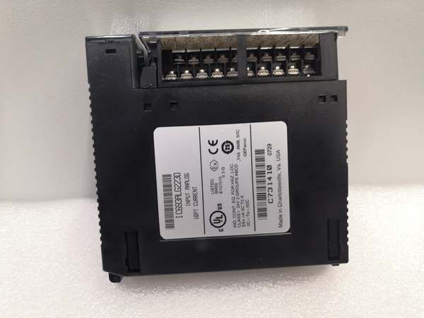
IC693ALG223
4. Product Introduction
The IC693ALG223-FR is a 16-channel analog current input module designed for the GE Fanuc Series 90-30 PLC platform, specifically engineered to interface with industrial transmitters and instruments outputting current loop signals. Each channel is individually configurable for three current ranges: standard 4-20 mA, 0-20 mA for zero-based applications, and 4-20 mA Enhanced with open-wire fault detection capability.
This unit delivers ±0.25% accuracy at room temperature with 12-bit resolution and 250Ω input impedance for standard current loop burden. The 19 Hz low-pass filter suppresses high-frequency noise, while the 13 ms update rate ensures responsive data acquisition for process control applications. Status is monitored via MODULE OK and USER SUPPLY OK LED indicators.
5. QA & Testing SOP
Our QC process for this 16-channel analog current input module follows a rigorous 5-step verification:
1. Incoming Inspection: We verify part numbers and revision levels against GE/Emerson datasheets. Physical inspection checks for corrosion, bent pins, counterfeit markings, or thermal damage on the terminal connector. We trace lot codes to confirm manufacturing origin and ensure firmware compatibility. Special attention is paid to the “FR” suffix to ensure it meets any regional-specific requirements, though specific details of such requirements were not identified in available documentation.
2. Live Testing: The module powers up in a Series 90-30 test rack with both +5 VDC backplane power and external +24 VDC supply connected. We inject calibrated current signals across all configured channels at 4 mA, 12 mA, and 20 mA for all three range configurations. A calibrated Fluke 773 milliamp clamp meter verifies readings within ±0.25% of expected values. We test Enhanced mode by simulating open-circuit conditions and confirming alarm triggers below 4 mA. All enabled channels are scanned simultaneously for 4 hours under full load to confirm stability.
3. Electrical Testing: Insulation resistance exceeds 10 MΩ between field side and logic side (measured at 500 VDC). We verify the 250Ω input impedance on each channel using a precision resistance meter. Cross-channel rejection is verified by injecting a 1 kHz signal on one channel and confirming no measurable interference on adjacent channels.
4. Firmware/Config Backup: We record the exact firmware version. Photo documentation captures the terminal block configuration and any jumper settings before testing begins. Configuration parameters are backed up for reference.
5. Final QC & Packaging: The module passes final visual inspection, receives a QC pass tag documenting measured values for all input points across all ranges, and ships in anti-static packaging. Each unit includes a test report verifying accuracy, resolution, and alarm functionality on all 16 channels.
6. Installation Pitfalls & Guide
❗ Missing External +24 VDC Supply
This unit requires an external +24 VDC supply (20-30 VDC range, 10% max ripple) to power the current loops. It draws 65 mA from this supply in addition to the loop currents themselves. Without this supply, the USER SUPPLY OK LED will not illuminate and current inputs will not function. Verify your external 24 VDC supply can handle the additional 65 mA load plus all loop currents (max 16 × 20 mA = 320 mA, total ~385 mA).
❗ Forgetting 250Ω Burden When Using Two-Wire Transmitters
Two-wire 4-20 mA transmitters require loop power. The module’s 250Ω input impedance provides adequate burden for most applications, but verify the transmitter’s minimum operating voltage requirements. Long cable runs with high resistance may drop too much voltage, causing the transmitter to drop below 4 mA or fail entirely. Calculate total loop resistance and ensure transmitter receives sufficient voltage (typically 12-24 VDC).
❗ Not Using Enhanced Mode for Critical Loops
If your application relies on detecting broken wires or failed transmitters, configure the channel for 4-20 mA Enhanced mode and set an appropriate low alarm threshold (typically 3.6-3.8 mA). Standard 4-20 mA mode cannot distinguish between 4 mA (process zero) and 0 mA (open circuit). Enhanced mode provides live-zero detection for fault identification.
❗ Exceeding External Supply Current Capacity
With 16 channels at 20 mA each plus the 65 mA module overhead, your external +24 VDC supply must provide up to 385 mA. An undersized supply causes voltage sag and inaccurate readings. Verify your external supply capacity and add 20-30% margin for reliability. Consider dedicated 24 VDC supplies for high-channel-count installations.
❗ Mixing 4-20 mA and 0-20 mA Without Updating PLC Scaling
Ranges are configurable per channel, but your PLC program must apply appropriate scaling factors for each channel. A 4-20 mA channel scaling 0-32000 counts represents 4-20 mA, while a 0-20 mA channel scaling 0-32000 counts represents 0-20 mA. Using identical scaling for different ranges causes significant process measurement errors. Document and implement proper scaling in your PLC program.
4-Step Replacement Guide:
- Pre-install: Document the channel configuration (range type per channel, active channel count, and alarm thresholds). Photograph the terminal block wiring noting which transmitters connect to each channel. Verify the external 24 VDC supply capacity.
- Removal: Power down the rack and external 24 VDC supply. Disconnect the terminal block wiring. Remove the failed module.
- Install: Install the replacement IC693ALG223-FR module. Reconnect the terminal block according to the documented wiring scheme. Ensure shield connections are properly terminated to COM or GND.
- Power-on Test: Apply power. Verify both LEDs illuminate (MODULE OK and USER SUPPLY OK). Inject known test currents (4, 12, 20 mA) to each configured channel and verify %AI values match expected readings within tolerance. Test Enhanced mode alarm functionality by breaking the loop and confirming low alarm triggers.

IC693ALG223
7. FAQ
Q: What does the “FR” suffix in IC693ALG223-FR indicate?
A: The exact meaning of the “FR” suffix is not explicitly documented in the available search results. Based on common GE Fanuc module naming conventions and ISO 3166 country codes, it is inferred that “FR” likely denotes a regional variant, possibly intended for the French market or compliance with specific European standards [Source: ISO 3166-1 FR Code]. However, without explicit confirmation from GE Fanuc, this remains a speculative interpretation. The core technical specifications of the IC693ALG223-FR appear identical to the base IC693ALG223 model. Verify with your supplier whether the suffix denotes specific regional requirements or non-standard modifications.
Q: Does this module support differential current inputs?
A: No. The module only supports single-ended current inputs. All 16 channels share a common return (COM). If you need differential inputs for noise immunity or ground isolation, consider using voltage input modules with differential capability (such as IC693ALG222) and external current-to-voltage converters, or install isolation barriers on critical loops.
Q: What’s the difference between 4-20 mA and 4-20 mA Enhanced modes?
A: Both ranges measure 4-20 mA currents, but Enhanced mode includes open-wire fault detection. In Enhanced mode, you can configure a low alarm threshold (typically 3.6-3.8 mA). If the loop opens and current drops below 4 mA, the alarm triggers, alerting the PLC to a transmitter or wiring failure. Standard 4-20 mA mode cannot distinguish between 4 mA (process zero) and 0 mA (open circuit). Use Enhanced mode for critical loops where fault detection is required.
Q: Can I mix different current ranges on the same module?
A: Yes. Each of the 16 channels can be independently configured for 4-20 mA, 0-20 mA, or 4-20 mA Enhanced. However, your PLC program must apply different scaling factors for each range type. Document which channels use which ranges and implement appropriate scaling in your PLC logic.
Q: What happens if a current loop opens (wire breaks)?
A: In standard 4-20 mA or 0-20 mA modes, the module reads 0 mA. In 4-20 mA Enhanced mode with a properly configured low alarm (e.g., 3.6 mA), the device detects the open circuit when current drops below the alarm threshold and sets the corresponding %I alarm bit. The PLC can then trigger an alarm, switch to backup sensors, or initiate safe shutdown procedures.


