
Description
Hard-Numbers: Technical Specifications
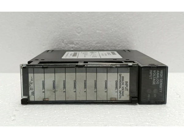
- Input Channels: 4 differential voltage inputs
- Voltage Ranges: ±10 V, ±5 V, 0-10 V, 1-5 V (hardware jumper selection)
- Resolution: 12-bit binary; 2.5 mV per LSB (±10V range); 1.25 mV per LSB (±5V range); 2.5 mV per LSB (0-10V range); 1.22 mV per LSB (1-5V range)
- Update Rate: 2 milliseconds for all 4 channels (0.5 ms per channel conversion)
- Absolute Accuracy: 0.1% full scale + 0.1% reading
- Linearity: < 1 LSB
- Input Impedance: > 1 megohm
- Isolation: 1500 V RMS between field side and logic side
- Common Mode Voltage: 150 V maximum
- Common Mode Rejection: > 70 dB at DC; > 70 dB at 60 Hz
- Cross-Channel Rejection: > 80 dB from DC to 1 kHz
- Input Filter Response: 325 Hz (-3dB)
- Power Consumption: 25 mA from +5VDC backplane; 100 mA from isolated +24VDC backplane
- Data Format: 16-bit 2’s complement in %AI registers
- Operating Temperature: 0°C to +60°C (32°F to 140°F)
- Storage Temperature: -40°C to +85°C (-40°F to +185°F)
- Humidity: 5–95% non-condensing

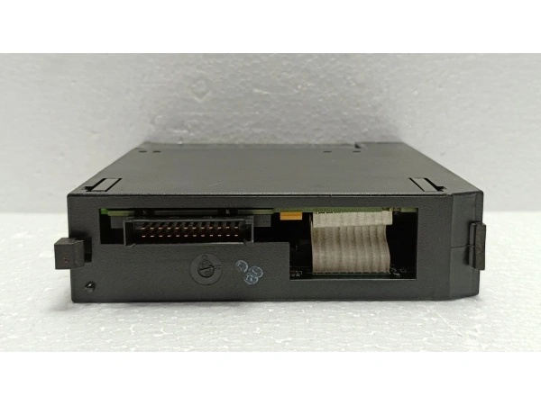
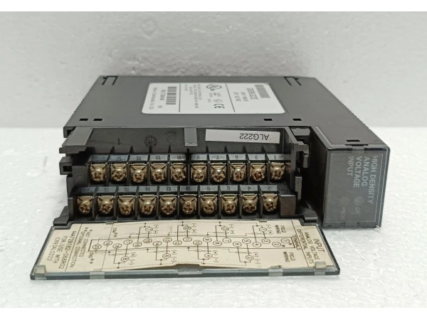
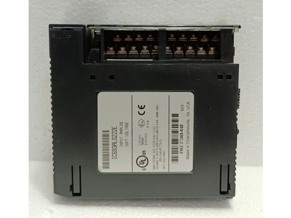
GE IC693ALG222E
The Real-World Problem It Solves
High-level voltage signals from position transducers, flow meters, and valve feedback devices need isolated, high-impedance conversion to digital values. The IC693ALG222E provides differential input with configurable voltage ranges and 1500V isolation, rejecting common-mode noise and preventing ground loops that corrupt measurements in harsh environments.
Where you’ll typically find it:
- Machine automation: Reading ±10V position feedback from linear transducers on hydraulic actuators and CNC machines
- Process control: Connecting 0-10V flow meters and pressure transmitters with voltage output in batch processing systems
- Material handling: Valve position feedback (1-5V) from pneumatic and hydraulic valve positioners
Bottom line: The IC693ALG222E converts high-level voltage signals to clean digital data with the isolation and input protection needed for industrial environments.
Hardware Architecture & Under-the-Hood Logic
The IC693ALG222E is a single-slot isolated voltage input module with four differential input channels. It uses hardware-configurable range selection via terminal block jumpers and a 12-bit successive-approximation ADC for each channel. No onboard microprocessor—pure analog-to-digital conversion with multiplexed ADCs and optical isolation.
-
Input Differential Stage
- Differential amplifier reads voltage between V+ and V- terminals, rejecting common-mode noise up to 150V
- High input impedance (>1MΩ) prevents loading the signal source
- Input protection clamps transients to ±30V; no reverse polarity protection on single-ended connections
-
Range Selection Hardware
- Two terminal block jumpers configure input ranges: jumper 1-2 for channels 1-2, jumper 3-4 for channels 3-4
- Jumper positions select ±10V, ±5V, 0-10V, or 1-5V ranges
- Range selection is purely hardware—no software configuration required
-
A/D Conversion Stage
- 12-bit successive-approximation ADC converts each channel sequentially
- 0.5 ms conversion time per channel, 2 ms total scan cycle for all four channels
- 325Hz low-pass filter removes high-frequency noise before digitization
- Internal 2.5V reference provides stable conversion accuracy
-
Optical Isolation Barrier
- Optical couplers transmit converted digital data across 1500V RMS isolation barrier
- Isolated +24VDC from backplane powers field-side electronics
- Separate ground references: COM (analog common) on field side, GND (backplane ground) on logic side
-
Data Scaling & Output
- Raw ADC counts scaled to full-range values based on selected range
- 16-bit 2’s complement format stored in %AI registers
- Over-range and under-range conditions clamp to minimum or maximum scale
- CPU reads data via Series 90-30 backplane bus during scan cycle
GE IC693ALG222E
Field Service Pitfalls: What Rookies Get Wrong
Confusing current and voltage inputs
Rookies wire a 4-20mA transmitter directly to the voltage input terminals. The high impedance doesn’t load the loop, so the transmitter swings to its compliance voltage limit—typically 24V—which fries the input protection network.
- Field Rule: Verify your transmitter output type before wiring. Voltage inputs are labeled V+ and V-; current inputs are labeled I+ and I-. If you need to read a 4-20mA loop, use a 250-ohm shunt resistor to convert to 1-5V before connecting to the voltage input.
Not using differential inputs properly
Rookies ground the V- terminal instead of using it as the differential return. Single-ended wiring kills common-mode rejection, and ground differentials between the transmitter and PLC introduce noise into the measurement.
- Field Rule: Use differential wiring whenever possible. Connect V+ to signal positive, V- to signal return, and COM to the isolated analog common—never to chassis ground unless the field device and PLC share the exact same ground reference.
Leaving the jumper in the wrong position
You configure your transmitter for 0-10V but leave the jumper in ±10V position. The module still reads the signal, but the scaling is wrong and your PLC interprets 5V as mid-scale instead of 50% of range.
- Field Rule: Verify jumper position before powering up. Label your terminal block with the configured range. If you’re unsure, check the transmitter spec sheet and match the jumper accordingly.
Forgetting to float COM when needed
Rookies tie the COM terminal to chassis ground in a system with multiple ground references. The common-mode voltage differential drives current through the module’s isolation barrier, causing erratic readings and possible damage.
- Field Rule: Keep COM floating when using differential inputs. Only connect COM to ground if the field device and PLC share the same ground reference and you’ve verified the ground potential difference is less than 1V.
Troubleshooting with a multimeter in voltage mode on a live loop
Rookies measure across the V+ and V- terminals with a multimeter while the loop is energized, causing a momentary load that drops the signal and trips the control loop.
- Field Rule: Use a high-impedance differential probe or isolate the loop before measuring. If you must use a multimeter, disconnect the module first or put the PLC in manual mode to prevent process upsets.
Not accounting for lead resistance on long runs
Rookies run 500 feet of 22AWG wire to a position transducer. The voltage drop across the wire resistance causes a 2-3% measurement error that gets blamed on the module.
- Field Rule: Use larger gauge wire (18AWG or 16AWG) for long cable runs over 300 feet. Calculate the voltage drop: Vdrop = I × R × 2 (round-trip distance). If drop exceeds 0.5% of full scale, relocate the transmitter or use a local 4-20mA loop with a shunt at the PLC.
Commercial Availability & Pricing Note
Please note: The listed price is for reference only and is not binding. Final pricing and terms are subject to negotiation based on current market conditions and availability.


