

Description
Hard-Numbers: Technical Specifications
- Input Channels: 4 single-ended current inputs
- Current Ranges: 4-20 mA (default) or 0-20 mA (via jumper)
- Resolution: 12-bit binary; 4 µA per LSB (4-20 mA range); 5 µA per LSB (0-20 mA range)
- Update Rate: 2 milliseconds for all 4 channels (0.5 ms per channel conversion)
- Absolute Accuracy: 0.1% full scale + 0.1% reading
- Linearity: < 1 LSB
- Input Impedance: 250 ohms
- Isolation: 1500 V RMS between field side and logic side
- Common Mode Voltage: 200 V maximum
- Common Mode Rejection: > 70 dB at DC; > 70 dB at 60 Hz
- Cross-Channel Rejection: > 80 dB from DC to 1 kHz
- Input Filter Response: 325 Hz (-3dB)
- Power Consumption: 25 mA from +5VDC backplane; 100 mA from isolated +24VDC backplane
- Data Format: 16-bit 2’s complement in %AI registers
- 4-20 mA Scaling: 4 mA = 0 counts; 20 mA = 32000 counts
- 0-20 mA Scaling: 0 mA = 0 counts; 20 mA = 32000 counts
- Operating Temperature: 0°C to +60°C (32°F to 140°F)
- Storage Temperature: -40°C to +85°C (-40°F to +185°F)
- Humidity: 5–95% non-condensing

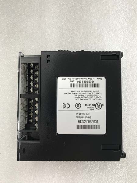
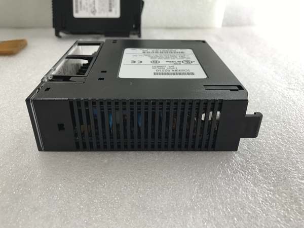
GE IC693ALG221
The Real-World Problem It Solves
Legacy Series 90-30 PLC systems still run critical processes, but the original analog input modules are failing after 20+ years of service. The IC693ALG221K provides factory-new replacement inventory for these obsolete systems, avoiding expensive control system upgrades while maintaining existing wiring and I/O configurations.
Where you’ll typically find it:
- Chemical processing plants: Replacing failed 4-20mA current input modules in aging GE Series 90-30 racks controlling reactor feed loops
- Pulp and paper mills: Swapping out dead current inputs on stock flow and headbox pressure transmitters in legacy DCS interfaces
- Power generation: Restoring analog input functionality on turbine governor systems that still use Series 90-30 PLCs for control
Bottom line: The IC693ALG221K lets you keep obsolete Series 90-30 systems running with new-old-stock hardware when a full system upgrade isn’t in the budget.
Hardware Architecture & Under-the-Hood Logic
The IC693ALG221K is an isolated current input module with four independent 12-bit A/D conversion channels. No onboard microprocessor—the module uses pure analog conversion hardware with multiplexed ADCs and hardware-configurable range selection via terminal jumpers. It communicates directly with the CPU over the Series 90-30 I/O bus, presenting scaled digital values in %AI registers.
-
Current-to-Voltage Conversion
- 250-ohm precision shunt resistor converts input current to 1-5V (4-20mA range) or 0-5V (0-20mA range)
- Differential input stage rejects common-mode noise up to 200V
- Input protection clamps transient overloads; no reverse polarity protection built-in
-
Range Selection Hardware
- Two terminal block jumpers control input ranges: jumper 1-2 for channels 1-2, jumper 3-4 for channels 3-4
- Jumper removed (default): 4-20mA range (4 mA = 0 counts, 20 mA = 32000 counts)
- Jumper installed: 0-20mA range (0 mA = 0 counts, 20 mA = 32000 counts)
- Range selection is purely hardware—no software configuration required
-
A/D Conversion Stage
- 12-bit successive-approximation ADC converts each channel sequentially
- 0.5 ms conversion time per channel, 2 ms total scan cycle for all four channels
- 325Hz low-pass filter removes high-frequency noise before digitization
- Internal 2.5V reference provides stable conversion accuracy
-
Optical Isolation Barrier
- Optical couplers transmit converted digital data across 1500V RMS isolation barrier
- Isolated +24VDC from backplane powers field-side electronics
- Separate ground references: COM (analog common) on field side, GND (backplane ground) on logic side
- Prevents ground loop currents from coupling into PLC backplane
-
Data Output to CPU
- Converted values stored in module registers mapped to %AI addresses
- 16-bit 2’s complement format; under-range inputs clamp to 0 counts, over-range clamp to 32000 counts
- CPU reads data via Series 90-30 backplane bus during scan cycle
- LED power indicator illuminates when both +5V and isolated +24V supplies are within spec

GE IC693ALG221
Field Service Pitfalls: What Rookies Get Wrong
Assuming “K” suffix means new production
The “K” suffix only indicates unused or new old stock—it doesn’t mean recently manufactured. These modules may have been sitting in a warehouse for 15+ years with dried electrolytic capacitors.
- Field Rule: Burn the unit in on a test bench for 48 hours under load before field deployment. Watch for erratic readings or excessive current draw—both indicate aging components.
Not verifying hardware revision
“K” units are not guaranteed to be Revision B. You might get an earlier revision with compatibility issues in newer CPU modules.
- Field Rule: Pull the module cover and read the revision silk-screened on the circuit board (IC693ALG221-XXXX). Confirm it matches your system requirements before installing in a live rack.
Leaving unused channels open
New techs disconnect a failed transmitter and leave the input channel floating. The open loop picks up noise and random values corrupt the %AI table.
- Field Rule: Short the + and – terminals of unused channels together with a jumper wire. This ties them to common mode and prevents floating inputs from generating garbage data.
Forgetting to update PLC scaling after jumper changes
You switch a channel from 4-20mA to 0-20mA by installing the jumper, but the PLC scaling block still expects the 4 mA zero offset.
- Field Rule: Update your PLC scaling blocks immediately after changing jumpers. 4-20mA uses a zero offset of 4 mA; 0-20mA starts at zero. Verify with a loop calibrator before trusting the reading.
Reversed polarity destroys input protection
Wire the current loop backward and current flows through the protection diodes the wrong way. The input circuit clamps to minimum scale (0000H) and can be permanently damaged.
- Field Rule: Verify polarity with a current clamp before connecting to the module. Transmitter positive to module input (+), transmitter negative to module return (-). If readings are stuck at zero, check polarity—don’t assume the transmitter is dead.
Commercial Availability & Pricing Note
Please note: The listed price is for reference only and is not binding. Final pricing and terms are subject to negotiation based on current market conditions and availability.


