
Description
Hard-Numbers: Technical Specifications
- Input Channels: 4 single-ended current inputs
- Current Input Ranges: 4-20 mA (default) or 0-20 mA (via jumper)
- Resolution: 12-bit binary; 4 µA per LSB (4-20 mA range), 5 µA per LSB (0-20 mA range)
- Update Rate: 2 milliseconds for all 4 channels (0.5 ms per channel conversion)
- Absolute Accuracy: 0.1% full scale + 0.1% reading
- Linearity: < 1 LSB (Least Significant Bit)
- Input Impedance: 250 ohms
- Isolation: 1500 V RMS between field side and logic side
- Common Mode Voltage: 200 V maximum
- Common Mode Rejection: > 70 dB at DC; > 70 dB at 60 Hz
- Cross-Channel Rejection: > 80 dB from DC to 1 kHz
- Input Filter Response: 325 Hz (-3dB)
- Power Consumption: 25 mA from +5VDC backplane; 100 mA from isolated +24VDC backplane
- Data Format: 16-bit 2’s complement in %AI registers
- 4-20 mA Scaling: 4 mA = 0 counts; 20 mA = 32000 counts (1000 counts = 0.5 mA)
- 0-20 mA Scaling: 0 mA = 0 counts; 20 mA = 32000 counts (800 counts = 0.5 mA)
- Range Configuration: Two jumpers provided—one for channels 1-2, another for channels 3-4
- Operating Temperature: 0°C to +60°C (32°F to 140°F)
- Storage Temperature: -40°C to +85°C (-40°F to +185°F)
- Humidity: 5–95% non-condensing
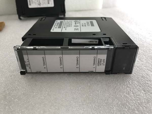
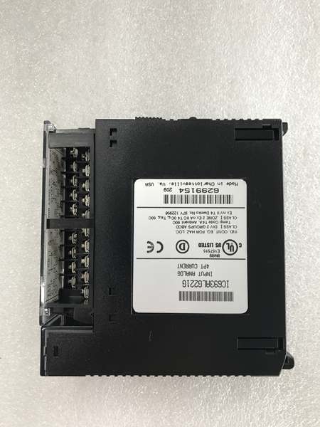
- Terminal Type: Removable terminal block with range jumpers
- Status Indicators: LED power indicator (ON = normal operation)

GE IC693ALG221
The Real-World Problem It Solves
Industrial 4-20mA current loops are the industry standard for noisy environments, but raw current signals still need conversion to digital values and isolation from ground potentials. The IC693ALG221 takes those 4-20mA transmitter outputs and converts them to reliable digital data the PLC can use for PID loops and trending—while keeping field transients off the backplane.
Where you’ll typically find it:
- Chemical processing plants: Flow transmitters, pressure transducers, and temperature transmitters using 4-20mA current loops
- Pulp and paper mills: Stock flow measurement, headbox pressure, and dryer temperature monitoring with 2-wire transmitters
- Oil & gas platforms: Pressure transmitters on separation trains, valve position feedback (4-20mA), and level transmitters
- Power generation: Turbine bearing temperature RTDs with 4-20mA transmitters, boiler drum level transmitters, and steam flow measurement
Bottom line: The IC693ALG221 bridges the gap between industry-standard 4-20mA transmitters and your Series 90-30 PLC—providing isolated, accurate current-to-digital conversion for process control loops.
Hardware Architecture & Under-the-Hood Logic
The IC693ALG221 is a single-slot isolated current input module with four independent A/D conversion channels. No microprocessor—the module is pure analog-to-digital conversion hardware with multiplexed ADC circuitry and hardware-configurable range selection via terminal jumpers. Each channel converts 4-20mA or 0-20mA current to digital values through a 250-ohm precision shunt resistor, presenting data to the CPU over the Series 90-30 I/O bus.
-
Input Current-to-Voltage Conversion:
- 250-ohm precision shunt resistor converts input current to voltage for A/D conversion
- 4-20mA input: produces 1-5V across shunt (0-20mA produces 0-5V)
- Low thermal coefficient resistor maintains accuracy over temperature range
- Input protection clamps transient overloads up to 200V common-mode
-
Range Selection via Jumpers:
- Two hardware jumpers on terminal block configure input range
- Jumper 1-2: sets channels 1 and 2 to 4-20mA (default) or 0-20mA
- Jumper 3-4: sets channels 3 and 4 to 4-20mA (default) or 0-20mA
- Jumper position determines scaling in module’s internal ADC logic
-
A/D Conversion Stage:
- 12-bit successive-approximation ADC with multiplexed input selection
- Conversion time: 0.5 ms per channel, 2 ms total scan cycle for all 4 channels
- 4-20mA range: resolution of 4 µA per LSB (4096 counts across 16mA span)
- 0-20mA range: resolution of 5 µA per LSB (4096 counts across 20mA span)
-
Optical Isolation Barrier:
- Digital data transmitted across isolation barrier via optocouplers
- 1500 V RMS isolation separates field wiring from logic side
- Prevents ground loops and common-mode noise from corrupting PLC logic
- Separate isolated +24VDC supply powers field side electronics
-
Data Scaling and Storage:
- 4-20mA scaling: 4 mA = 0 counts, 20 mA = 32000 counts (1000 counts = 0.5 mA)
- 0-20mA scaling: 0 mA = 0 counts, 20 mA = 32000 counts (800 counts = 0.5 mA)
- Data stored in 16-bit 2’s complement format in %AI registers
- Reversed polarity or out-of-range inputs clamp to minimum or maximum scale
-
Power Distribution:
- +5VDC from backplane powers logic side electronics
- Isolated +24VDC from backplane powers field side and shunt resistor
- Internal DC-DC converter generates isolated analog supply voltages
- LED indicator illuminates when both supplies are within spec
-
Diagnostic Circuitry:
- Power good monitoring detects supply voltage failures
- Open-circuit detection flags broken current loops (below 4mA in 4-20mA mode)
- Overrange detection triggers fault flag if input exceeds 21 mA
- No module-to-module communication—diagnostics reported via status word

GE IC693ALG221
Field Service Pitfalls: What Rookies Get Wrong
Misconfigured range jumpers
Rookies wire a 0-20mA transmitter but leave the jumper in 4-20mA position. The module interprets the 0-4mA range as “below 4mA” (fault condition) and reads zero, causing the PLC to think the transmitter is dead.
- Field Rule: Verify jumper position before powering up. 4-20mA is default—install jumper for 0-20mA range. Label your terminal block with the configured range so future techs don’t assume default.
Leaving current loops open
Rookies disconnect a transmitter for maintenance but leave the input channel configured. The open loop floats near zero, and the PLC interprets it as “0 mA” (or 4 mA fault in 4-20mA mode), driving outputs to wrong positions.
- Field Rule: If a transmitter is disconnected, either short the channel at the module (tie the input terminals together through a 500-ohm resistor) or disable the channel in software. Don’t trust open-circuit readings.
Not accounting for the 250-ohm shunt
Rookies wire a 4-20mA transmitter and then try to measure voltage across the input terminals with a multimeter, wondering why they’re reading 1-5V instead of 0-5V. The internal 250-ohm shunt drops voltage, and this confuses troubleshooting.
- Field Rule: The module has a built-in 250-ohm shunt. Voltage across the terminals will be 1-5V (4-20mA range) or 0-5V (0-20mA range). Don’t expect 0V—measure current in series if you need to verify loop continuity.
Mixing 4-20mA and 0-20mA on the same jumper pair
Rookies set the jumper for 4-20mA for channel 1 but 0-20mA for channel 2. Since one jumper controls both channels 1-2, the configuration is ambiguous and both channels may read erratically.
- Field Rule: Each jumper controls a pair of channels. Jumper 1-2 covers channels 1 and 2; jumper 3-4 covers channels 3 and 4. If you need mixed ranges, put them on separate jumper pairs or use two modules.
Ignoring shield grounding on current loops
Rookies figure “it’s current, not voltage” and leave the shield ungrounded. The unshielded loop picks up EMI from nearby VFDs, and the mA reading jitters by 0.5-1 mA—enough to throw off tight PID tuning.
- Field Rule: Ground the shield drain wire at the module’s COM terminal, not chassis ground. Current loops are less sensitive to noise than voltage signals, but long runs near power equipment still need shielding.
Troubleshooting with the loop powered up
Rookies try to disconnect a transmitter while the loop is energized, causing a spark and potentially damaging the module’s input protection diodes. Or they insert a multimeter in series while the loop is live, causing momentary dropouts.
- Field Rule: Power down the transmitter or the module before breaking the loop. If you must troubleshoot hot, use a current clamp meter—don’t break the loop with a multimeter. The 250-ohm shunt can only handle so much.
Not calibrating after changing ranges
Rookies switch a channel from 4-20mA to 0-20mA but keep the same scaling in the PLC program. The 0-4mA dead band in 4-20mA mode disappears, and the zero offset throws off the entire control loop.
- Field Rule: When changing ranges, update your PLC scaling blocks. 4-20mA uses a zero offset of 4 mA; 0-20mA starts at zero. Re-verify your engineering units and PID tuning after range changes.
Assuming common-mode immunity is infinite
Rookies route 4-20mA loops next to 480V motor leads, thinking “current loops are immune to noise.” Common-mode coupling still induces errors, and the 200V rating is reduced performance—not immunity.
- Field Rule: Maintain at least 6 inches separation from power cables. The 200V common-mode rating means the module will tolerate some offset but with reduced accuracy. For best performance, keep current loops isolated from high-voltage wiring.
Reversed polarity not detected
Rookies wire a transmitter backwards and wonder why the reading is zero. Reversed polarity drives current backward through the protection diodes, and the module clamps to the minimum scale (0000H in %AI register).
- Field Rule: Verify polarity with a current clamp meter before trusting the reading. Transmitter positive to module input (+), transmitter negative to module return (-). If the reading is stuck at zero, check polarity first.
Commercial Availability & Pricing Note
Please note: The listed price is for reference only and is not binding. Final pricing and terms are subject to negotiation based on current market conditions and availability.


