
Description
Hard-Numbers: Technical Specifications
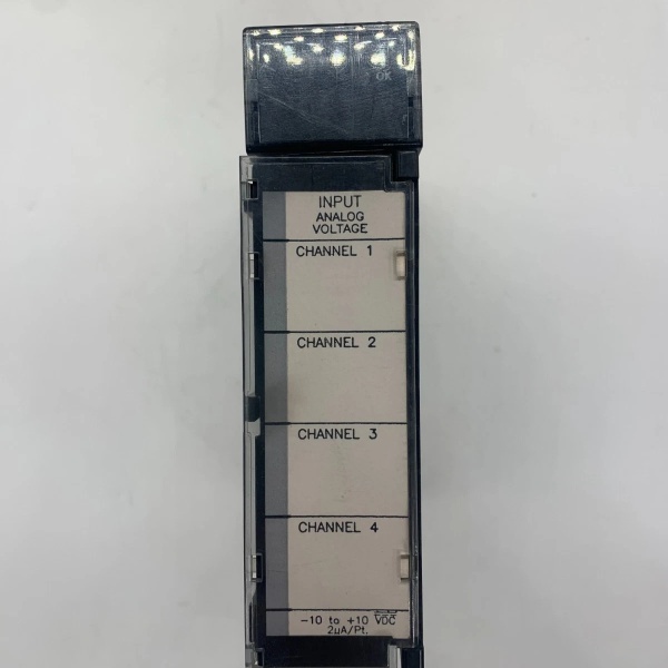
- Input Channels: 4 differential voltage inputs
- Voltage Range: -10 to +10 VDC (factory calibrated)
- Current Input Range: -40 to +40 mA (with internal 250Ω shunt jumper installed)
- Resolution: 12-bit binary (4096 counts); 5 mV per LSB (voltage mode), 20 µA per LSB (current mode)
- Update Rate: 4 milliseconds for all 4 channels (1 ms per channel conversion speed)
- Absolute Accuracy: ±10 mV/±40 µA typical; ±30 mV/±160 µA maximum over operating temperature
- Linearity: < 1 LSB (Least Significant Bit)
- Input Impedance: > 9 MΩ (voltage mode); 250 Ω (current mode)
- Isolation: 1500 V RMS between field side and logic side
- Cross-Channel Rejection: > 80 dB
- Input Filter Response: 17 Hz (-3dB)
- Common Mode Voltage: ±200 V maximum relative to COM
- Power Consumption: 27 mA from +5VDC backplane; 98 mA from isolated +24VDC backplane
- Data Format: 16-bit 2’s complement in %AI registers; scaling: 0V = 0 counts, +10V = 32000 counts
- Operating Temperature: 0°C to +60°C (32°F to 140°F)
- Storage Temperature: -40°C to +85°C (-40°F to +185°F)
- Humidity: 5–95% non-condensing
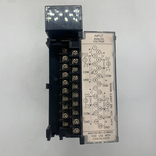
- Terminal Type: Removable 40-pin terminal connector with individual jumpers for current mode selection
- Status Indicators: LED power indicator (ON = normal operation)

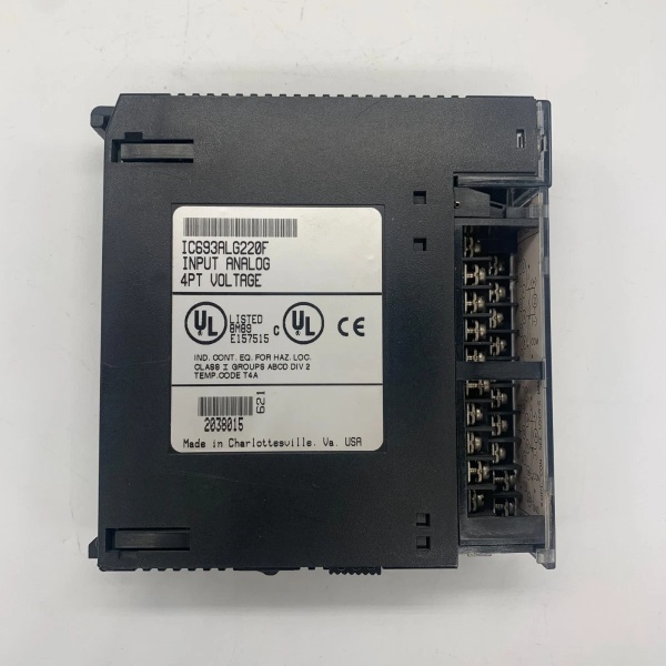
IC693ALG220
The Real-World Problem It Solves
Process sensors output millivolt-level signals that get corrupted by noise, ground loops, and EMI in industrial plants. The IC693ALG220 provides isolated, high-resolution conversion of these fragile analog signals into clean digital values the PLC can use for control loops and PID algorithms. Without proper isolation and filtering, your temperature, pressure, and flow readings drift randomly—causing unstable process control and wasted product.
Where you’ll typically find it:
- Chemical processing plants: Monitoring reactor temperatures, pressures, and flow rates for batch control loops
- Pulp and paper mills: Headbox pressure sensing, stock flow measurement, and dryer temperature control
- Oil & gas platforms: Pressure transmitter inputs, valve position feedback, and temperature monitoring on separation trains
- Power generation: Turbine bearing temperature monitoring, boiler drum level transmitters, and steam flow measurement
Bottom line: The IC693ALG220 is your frontline defense against analog signal corruption—turning noisy sensor voltages into reliable data your control logic can trust.
Hardware Architecture & Under-the-Hood Logic
The IC693ALG220 is a single-slot isolated analog input module containing four independent A/D conversion channels with optical isolation between field inputs and the PLC backplane. No microprocessor—the module is pure analog-to-digital conversion hardware with multiplexed ADC circuitry. The 12-bit successive-approximation ADC converts each channel sequentially, stores values in internal registers, and presents data to the CPU over the Series 90-30 I/O bus.
-
Input Multiplexing Stage:
- Four differential input channels routed through solid-state multiplexer
- Each channel filtered by 17 Hz RC low-pass network before ADC
- Input protection circuitry clamps transient voltages to ±30 V
- Jumper selection on terminal connector inserts 250Ω shunt resistor for current mode
-
A/D Conversion Stage:
- 12-bit successive-approximation ADC with 5 mV resolution
- Conversion time: 1 ms per channel, 4 ms total scan cycle
- Sample-and-hold circuit freezes signal during conversion
- Reference voltage derived from internal precision reference (±10 V nominal)
-
Optical Isolation Barrier:
- Digital data transmitted across isolation barrier via optocouplers
- 1500 V RMS isolation separates field wiring from logic side
- Prevents ground loops and common-mode noise from corrupting PLC logic
- Separate isolated +24VDC supply powers field side electronics
-
Data Scaling and Storage:
- Raw 12-bit data aligned in 16-bit 2’s complement format
- Scaling: -10V = -32000 counts, 0V = 0 counts, +10V = +32000 counts
- Current mode scaling: 4-20 mA maps to 1-5 V input (8000-16000 counts)
- Data buffered in module registers until CPU reads via %AI addressing
-
Power Distribution:
- +5VDC from backplane powers logic side electronics
- Isolated +24VDC from backplane powers field side and ADC
- Internal DC-DC converter generates isolated analog supply voltages
- LED indicator illuminates when both supplies are within spec
-
Diagnostic Circuitry:
- Power good monitoring detects supply voltage failures
- Open-circuit detection flags disconnected sensor wires
- Overrange detection triggers fault flag if input exceeds ±11 V
- No module-to-module communication—diagnostics reported via status word
IC693ALG220
Field Service Pitfalls: What Rookies Get Wrong
Forgetting the current mode jumper
Rookies wire a 4-20 mA transmitter to the input terminals but leave the shunt jumper removed. The module sees 0 mA input (open circuit) and the PLC reads random noise or minimum scale values, causing the control loop to drive the output full-scale.
- Field Rule: For 4-20 mA current inputs, install the jumper on the terminal connector for that channel to engage the internal 250Ω shunt resistor. Verify jumper position before powering up—current mode won’t work without it.
Leaving unused inputs floating
Rookies leave disconnected inputs open-circuited. The floating inputs pick up EMI and oscillate randomly in the %AI table, causing background noise that corrupts trending data and alarm thresholds.
- Field Rule: Short the + and – terminals together for all unused inputs. This ties them to common mode and prevents random fluctuations. Don’t rely on the transmitter being powered off—physically jumper the terminals.
Ignoring shield grounding
Rookies connect the cable shield to terminal ground instead of the COM terminal, creating ground loops that introduce 60 Hz hum into analog readings. The process variable jitters and PID hunting drives operators crazy.
- Field Rule: Connect the shield drain wire to the COM terminal on the analog module—not to chassis ground. COM is the isolated analog common; chassis ground is for the backplane. Keep them separate unless your grounding diagram says otherwise.
Overloading the current input
Rookies push 20+ mA through the internal shunt resistor, thinking “it’s only 5 mA over spec.” The resistor heats up, drifts in value, and your calibration shifts by 2–3%—wasting an entire production batch before anyone notices.
- Field Rule: Never exceed ±20 mA in current mode. The shunt resistor is rated for ±40 mA absolute max but accuracy degrades above ±20 mA due to self-heating. If you need higher current, use an external precision resistor and calculate the scaling.
Mixing single-ended and differential wiring
Rookies wire one channel single-ended (signal to +, ground to –) and another differential (signal + and –), assuming both work the same. The single-ended channel has poor noise rejection and reads garbage when nearby equipment starts up.
- Field Rule: Always wire differential for noise immunity. Connect the signal positive to + terminal, signal negative to – terminal, and wire shield to COM. If you must wire single-ended (floating sensor only), tie the – terminal to COM at the module.
Not accounting for the 17 Hz filter
Rookies try to read fast-changing signals (pressure spikes, vibration transducers) and complain the data is sluggish or smoothed out. The 17 Hz input filter intentionally suppresses high-frequency content that would alias into the digital readings.
- Field Rule: The 17 Hz filter is intentional—it eliminates noise above 60 Hz mains frequency. If you need faster response, use a dedicated high-speed analog module. Don’t defeat the filter—the readings will be noisy and unreliable.
Misinterpreting the scaling
Rookies assume 0-10V maps to 0-32000 counts linearly and wonder why -10V reads as negative values. The module uses bipolar scaling centered at 0V, not unipolar 0-based scaling.
- Field Rule: The IC693ALG220 uses bipolar scaling: -10V = -32000 counts, 0V = 0 counts, +10V = +32000 counts. For 0-10V sensors, either offset in software or use a unipolar module. Don’t rewire to force bipolar sensors into unipolar mode.
Troubleshooting with the module powered up
Rookies try to trace wiring with the PLC running, probing terminals with a multimeter. The active inputs drive current into the meter, causing temporary glitches that trigger alarms or shutdown sensitive control loops.
- Field Rule: Always power down the module or place the PLC in PROGRAM mode before troubleshooting wiring. Analog inputs are live when powered—probing loads the circuit and corrupts readings. If you must troubleshoot hot, use a high-impedance meter (10 MΩ minimum) and expect temporary fluctuations.
Ignoring isolation limits
Rookies assume the 1500V isolation protects against any fault and wire the module directly to 480V MCCs without transient protection. A nearby lightning strike or motor fault couples high-voltage transients through capacitance, frying the optocouplers.
- Field Rule: Install transient voltage suppressors (TVS diodes or MOVs) on field inputs in high-exposure areas. The 1500V isolation is for steady-state, not lightning or inductive kickback. Treat the field side as if it’s exposed—add surge protection if wiring runs long distances near power equipment.
Commercial Availability & Pricing Note
Please note: The listed price is for reference only and is not binding. Final pricing and terms are subject to negotiation based on current market conditions and availability.


