
Description
Hard-Numbers: Technical Specifications
- Module Type: I/O Bus Isolator/Repeater
- Function: Signal regeneration and galvanic isolation
- Isolation Voltage: 1500V RMS between input and output sections
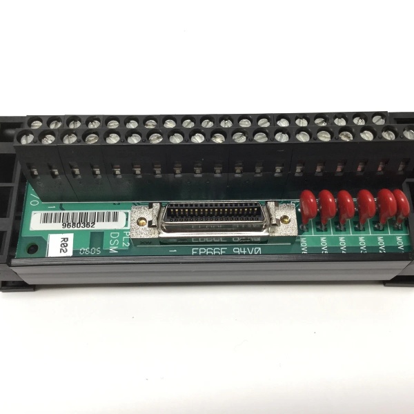
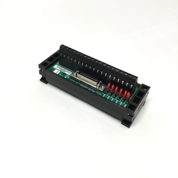
- Input Connector: 25-pin D-sub female (for incoming I/O bus)
- Output Connector: 25-pin D-sub female (for outgoing I/O bus)
- Power Supply: Requires +5VDC from baseplate (no external power needed)
- Current Draw: 350mA maximum from +5VDC backplane
- Propagation Delay: <100ns typical
- Operating Temperature: 0°C to +55°C (+32°F to +131°F)
- Storage Temperature: -40°C to +85°C (-40°F to +185°F)
- Humidity: 5–95% non-condensing
- Dimensions: Slot-mounted module, standard Series 90-30 form factor
- Weight: 0.3 kg (0.7 lbs)
- Status Indicators: LED indicators for power and bus activity on input/output sides
The Real-World Problem It Solves
IC693ACC336
Ground loops kill I/O bus communications in distributed systems. When you have expansion racks in different buildings, on different power transformers, or separated by long cable runs, the voltage potential difference between locations corrupts I/O bus signals and causes intermittent faults that are a nightmare to troubleshoot. The IC693ACC336 breaks the ground reference and regenerates clean signals.
Where you’ll typically find it:
- Multi-building installations: Paper mills where I/O racks span separate process buildings on different electrical services
- Offshore platforms: Topsides modules with separate grounding systems where ground potentials differ significantly
- Long-distance expansions: Refinery units requiring I/O racks beyond the 50-foot limit of standard expansion cables
- High-noise environments: Steel mills and foundries with heavy VFD loads that induce ground currents
Bottom line: The IC693ACC336 is your insurance policy against ground loops and signal degradation in distributed I/O systems.
Hardware Architecture & Under-the-Hood Logic
The IC693ACC336 is an active signal conditioning module that provides galvanic isolation between two segments of the Series 90-30 I/O bus. Unlike passive terminators or simple repeaters, it uses optical isolation to break the ground reference between input and output sides while regenerating fresh signals for the downstream bus segment.
-
Input Signal Reception:
- 25-pin D-sub connector receives I/O bus signals from upstream baseplate
- Differential receivers extract data, clock, and control signals from incoming bus
- Input protection circuitry guards against voltage spikes and transients
- Signal conditioning amplifies and cleans incoming signals before isolation
-
Galvanic Isolation Barrier:
- Optical couplers transmit digital signals across isolation barrier
- 1500V RMS isolation voltage rating protects downstream equipment from ground faults
- Separate ground references maintained between input and output sections
- Isolation barrier blocks common-mode noise and ground loop currents
-
Signal Regeneration:
- Transmitter circuits on output side regenerate fresh bus signals
- Output drivers restore signal amplitude and rise/fall times to specification
- Regenerated signals eliminate accumulated noise and jitter from upstream segment
- Bidirectional communication supported for full-duplex I/O bus operation
-
Power Distribution:
- Draws +5VDC from local baseplate backplane
- Internal DC-DC converters provide isolated power for output section
- No external power supply required
- Power isolation complements signal isolation for complete ground break
-
Status Monitoring:
- LED indicators display power status for input and output sections
- Bus activity LEDs show data transmission on both sides
- Fault detection circuitry flags isolation barrier failures
- No communication with CPU—purely hardware-level isolation

IC693ACC336
Field Service Pitfalls: What Rookies Get Wrong
Installing the isolator backward
Rookies plug the input side to the downstream rack and output side to the upstream rack. The module still shows power LEDs, but the I/O bus won’t communicate because the signal direction is reversed and the isolation barrier is oriented wrong.
- Field Rule: The IN port connects to the CPU side (upstream), and the OUT port connects to the expansion side (downstream). Trace your I/O bus from the CPU outward—the IC693ACC336 goes between segments with IN toward the CPU.
Assuming the isolator eliminates all termination requirements
Rookies install IC693ACC336 in the middle of an expansion chain and remove the IC693ACC307 terminator from the final rack, thinking the isolator somehow handles termination. The unterminated bus still causes reflections on both sides.
- Field Rule: The IC693ACC336 does NOT terminate the bus. Each isolated segment of the I/O bus requires its own termination. Install IC693ACC307 on the last baseplate of the final segment. If you have multiple isolated segments, each needs proper termination.
Creating unnecessary isolation points
Rookies install IC693ACC336 between every pair of expansion racks “just to be safe,” adding unnecessary complexity and points of failure. Each isolator adds propagation delay and current draw that can impact system performance.
- Field Rule: Install IC693ACC336 only where you actually need ground isolation or signal regeneration. Typical scenarios: crossing building boundaries, different power transformers, or cable runs exceeding 50 feet. One well-placed isolator beats six poorly placed ones.
Ignoring the current draw on the local baseplate
The IC693ACC336 draws 350mA from the +5VDC backplane. Rookies add it to an already-loaded baseplate without checking power budget, then wonder why the rack experiences brownouts or intermittent module failures under full load.
- Field Rule: Add 350mA to your +5VDC power budget for each IC693ACC336 installed. Verify your power supply can handle the additional load. If you’re near the limit, relocate the isolator to a less-loaded baseplate or add a second power supply.
Misinterpreting LED status indicators
The IC693ACC336 has separate LEDs for input power, output power, and bus activity. Rookies see one side lit up and assume the whole module is working, missing a dead output side that’s killing communication to downstream racks.
- Field Rule: Both input and output LEDs must be lit for proper operation. If only one side is lit, the isolation barrier or internal power converter has failed. Check bus activity LEDs on both sides during normal operation—both should flash when I/O traffic is present.
Installing without proper grounding
Rookies assume the IC693ACC336 doesn’t need grounding because it “isolates” the bus. The module’s metal backplane still needs proper chassis ground for EMI shielding and fault protection.
- Field Rule: Ensure the IC693ACC336 module is properly grounded through the baseplate. Verify the baseplate mounting screws make good contact with the enclosure ground. The isolation barrier breaks signal grounds, not chassis ground.
Using the isolator to fix unrelated bus problems
Rookies install IC693ACC336 to “fix” I/O bus issues caused by bad cables, incorrect termination, or overloading. When the problem persists, they add more isolators instead of addressing the root cause.
- Field Rule: The IC693ACC336 only solves ground loop, isolation, and signal regeneration problems. It won’t fix bad cables, missing terminators, or overloaded backplanes. Troubleshoot the root cause before installing hardware band-aids.
Forgetting to document isolation points in system drawings
Rookies install IC693ACC336 in the field without updating as-built drawings. Months later during troubleshooting, engineers chase ghost problems because they don’t know the system has isolation points that affect grounding strategy.
- Field Rule: Document every IC693ACC336 installation in your system drawings. Mark isolated segments and note the ground reference for each. This is critical for future maintenance and troubleshooting.
Commercial Availability & Pricing Note
Please note: The listed price is for reference only and is not binding. Final pricing and terms are subject to negotiation based on current market conditions and availability.


