
Description
Hard-Numbers: Technical Specifications
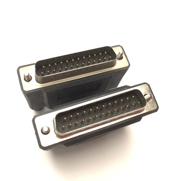
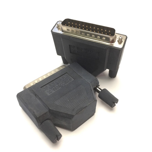
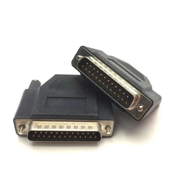
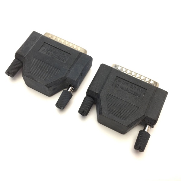
- Connector Type: 25-pin D-sub connector (female)
- Resistor Pack: Yes (integrated termination resistors)
- Supported Expansion Cables: IC693CBL302, IC693CBL314
- Maximum Expansion Cable Length: 15 meters (50 feet)
- Mounting: Installs in last expansion baseplate connector
- System Operating Temperature: 0°C to +55°C (+32°F to +131°F)
- System Storage Temperature: -40°C to +85°C (-40°F to +185°F)
- Weight: 0.11–0.3 lbs (0.05–0.14 kg)
- Dimensions: Varies by source (approximately 3.5 × 13 × 13.5 cm)
- Compatibility: All Series 90-30 PLC baseplates and CPUs
- Applications: Packaging, material handling, food processing, and other industrial automation applications
- Status: Discontinued/Obsolete (still available as surplus/refurbished)
- Revisions: IC693ACC307A (Revision A)

GE IC693ACC307
The Real-World Problem It Solves
Multi-baseplate Series 90-30 systems require proper bus termination to prevent signal reflections, communication errors, and intermittent I/O failures. The IC693ACC307 terminates the I/O expansion bus when multiple baseplates are cabled together, ensuring reliable signal transmission between the CPU and remote I/O modules.
Where you’ll typically find it:
- Multi-rack expansion systems: Systems with 2–8 baseplates requiring I/O bus extension beyond the CPU rack.
- Remote I/O installations: Applications where I/O modules are located remotely from the CPU, connected via expansion cables.
- Large control systems: Packaging lines, material handling systems, and food processing plants with distributed I/O requirements.
Bottom line: It’s a low-cost component that prevents high-impact system failures. Without proper termination, expansion systems will experience intermittent communication errors, I/O module dropouts, and unpredictable behavior.
Hardware Architecture & Under-the-Hood Logic
The IC693ACC307 is a passive terminator plug containing resistor networks that match the characteristic impedance of the I/O expansion bus. It terminates the bus at the far end of the expansion chain, preventing signal reflections that cause data corruption.
-
Resistor Network:
- Contains termination resistors (typically 82–120Ω range) matched to the I/O bus characteristic impedance.
- Resistor pack is physically mounted inside the 25-pin connector housing.
- Provides both AC termination (for signal integrity) and DC termination (for proper bias voltage).
-
Connector Interface:
- 25-pin D-sub female connector plugs into the expansion baseplate connector.
- Pinout matches Series 90-30 I/O bus expansion specification.
- Locking mechanism ensures secure connection and prevents vibration-induced disconnects.
-
Installation Location:
- Critical: Must be installed only in the last expansion baseplate in the chain.
- For single expansion baseplate systems, can use either IC693ACC307 terminator plug OR IC693CBL302/IC693CBL314 cable with built-in termination resistors.
- For systems with multiple expansion baseplates (2 or more), use IC693ACC307 on the final baseplate and standard expansion cables between intermediate baseplates.
-
Signal Integrity Function:
- Absorbs signal reflections caused by impedance mismatches at the end of the bus.
- Prevents ringing and overshoot on the I/O bus signals.
- Ensures reliable data transmission between CPU and remote I/O modules.
-
No Active Components:
- Passive device—no power required.
- No diagnostics or status indication.
- Does not communicate with the CPU or I/O modules.
GE IC693ACC307
Field Service Pitfalls: What Rookies Get Wrong
Installing the terminator in the wrong baseplate
The most common rookie error: installing IC693ACC307 in an intermediate baseplate instead of the last one. This causes bus reflections at both ends of the chain, leading to severe communication errors and I/O failures.
- Field Rule: Identify the last expansion baseplate in the chain (the one furthest from the CPU rack). Install IC693ACC307 only in this baseplate. Verify by tracing the expansion cables from the CPU rack outward.
Using IC693ACC307 AND terminated expansion cables simultaneously
Some expansion cables (IC693CBL302, IC693CBL314) have built-in termination resistors. Rookies install IC693ACC307 terminator plug AND use terminated cables on the same bus, creating double termination and causing signal degradation.
- Field Rule: Use either IC693ACC307 terminator plug OR terminated expansion cables, not both. If using IC693ACC307, use unterminated expansion cables between baseplates. If using terminated cables as the final cable, do not install IC693ACC307.
Ignoring the need for termination in short expansions
Rookies assume short expansion systems (under 5 meters) don’t need termination. They omit IC693ACC307, then experience intermittent I/O errors that are difficult to diagnose.
- Field Rule: Any expansion system with one or more expansion baseplates requires proper termination. Install IC693ACC307 in the last baseplate regardless of cable length—GE specifies termination for all expansion configurations.
Failing to secure the connector properly
The 25-pin connector can vibrate loose in high-vibration environments. Rookies hand-tighten the connector screws, then experience intermittent bus errors when machines are running.
- Field Rule: Tighten connector screws to specified torque (typically 6–8 in-lbs). Apply thread-locking compound in high-vibration applications. Verify secure connection by gently tugging on the connector after installation.
Mixing Series 90-30 and Series 90-70 components on the same expansion bus
Rookies attempt to use IC693ACC307 with Series 90-70 expansion cables or baseplates, assuming compatibility across product families. This causes mismatched impedance and communication failures.
- Field Rule: IC693ACC307 is designed for Series 90-30 systems. Do not mix with Series 90-70 expansion components unless explicitly specified by GE. Series 90-70 requires its own termination devices.
Not replacing damaged or corroded terminators
The resistor pack can degrade over time, especially in harsh environments. Rookies assume the terminator “never fails” and leave corroded or physically damaged terminators in service, leading to increased bit error rates.
- Field Rule: Inspect IC693ACC307 during preventive maintenance. Check for corrosion on pins, physical damage to the housing, or signs of overheating. Replace any suspect terminators immediately—passive components do fail in industrial environments.
Assuming the terminator provides diagnostics
Rookies troubleshoot expansion system errors by looking for fault codes from IC693ACC307. They waste time searching for diagnostics that don’t exist.
- Field Rule: IC693ACC307 is a passive device with no diagnostics. If expansion errors occur, check cable continuity, connector seating, and terminator placement. Use the CPU’s I/O diagnostics to identify failing modules or cable segments.
Leaving unused expansion slots unterminated
In systems with potential for future expansion, rookies leave unused expansion baseplate connectors open. This causes unterminated stubs that reflect signals and degrade bus performance.
- Field Rule: Cap any unused expansion connectors with IC693ACC307 terminator plugs or blanking plates. This prevents stub reflections and maintains proper bus impedance throughout the system.
Commercial Availability & Pricing Note
Please note: The listed price is for reference only and is not binding. Final pricing and terms are subject to negotiation based on current market conditions and availability.


