
Description
Hard-Numbers: Technical Specifications
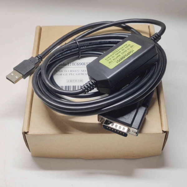
- Interface 1: USB Type-A connector (device side, connects to PC)
- Interface 2: Profibus-DP connector (typically 9-pin D-sub male)
- Protocol Support: Profibus-DP V0/V1 (master and slave support)
- Communication Speed: 9.6 Kbit/s to 12 Mbit/s (configurable)
- Electrical Interface: RS485 differential signaling
- Power Supply: Bus-powered via USB (no external power required)
- LED Indicators: Power, Transmit, Receive, and Error status LEDs
- Operating Temperature: 0°C to +50°C
- Storage Temperature: -20°C to +70°C
- Relative Humidity: 10% to 90% (non-condensing)
- EMC: CE, FCC compliance
- Driver Support: Windows 7/8/10/11 (32/64-bit)
- Cable Length: Maximum Profibus segment length depends on baud rate (typically 100–1200m)

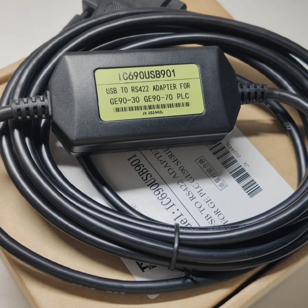
IC690USB901
The Real-World Problem It Solves
This adapter provides a bridge between modern PCs lacking native serial ports and Profibus-DP industrial networks. It enables technicians and engineers to configure PLCs, monitor network traffic, and diagnose Profibus devices without legacy hardware.
Where you’ll typically find it:
- PC/laptop Profibus access: Connecting maintenance laptops to Profibus networks for configuration and diagnostics.
- PLC programming: Programming GE Fanuc, Siemens, and other Profibus-compatible controllers.
- Network troubleshooting: Monitoring Profibus bus traffic, detecting signal reflections, and identifying failed nodes.
- Device commissioning: Configuring new Profibus slave devices such as I/O modules, drives, and sensors.
Bottom line: It’s the essential tool for anyone working with Profibus-DP networks in modern PC environments. Without it, you’d need a legacy PC with a dedicated Profibus interface card.
Hardware Architecture & Under-the-Hood Logic
This is a USB-to-serial converter with built-in Profibus-DP protocol stack. It translates USB data from the PC into Profibus DP telegrams on the RS485 bus and vice versa.
-
USB Interface Layer:
- USB 2.0 full-speed (12 Mbit/s) connection to host PC.
- Virtual COM port (VCP) drivers present the device as a standard serial port to applications.
- USB provides both communication and power to the converter.
-
Profibus-DP Protocol Layer:
- Internal firmware implements Profibus-DP V0/V1 protocol stack.
- Supports both master and slave operation modes (configurable via software).
- Handles token passing, telegram transmission, and error detection.
- Configurable baud rates from 9.6 Kbit/s to 12 Mbit/s.
-
RS485 Physical Layer:
- Differential signaling on A/B lines for noise immunity in industrial environments.
- Supports up to 32 nodes per segment without repeaters.
- Integrated termination resistor (typically 150Ω) can be enabled via switch or jumper.
-
Status Indication:
- Power LED: USB power present
- TX/RX LEDs: Data transmission activity on the bus
- Error LED: Detected bus errors (collisions, timeouts, signal integrity issues)
-
Driver Integration:
- VCP drivers create virtual serial port (COMx) on Windows systems.
- Compatible with Profibus configuration software (Siemens STEP 7, GE Proficy Machine Edition, etc.)
- Configuration utilities allow baud rate selection and termination control.
IC690USB901
Field Service Pitfalls: What Rookies Get Wrong
Incorrect termination resistor settings
Profibus networks require 220Ω termination at both ends of the bus. Rookies leave the converter’s termination disabled when connected to the end of the network, causing signal reflections and intermittent communication failures.
- Field Rule: Enable the termination resistor on the converter if it’s connected to the first or last node on the Profibus segment. Use an ohmmeter to verify 220Ω between A and B lines when enabled.
Forgetting to install drivers
The converter requires a VCP driver to create a virtual COM port. Rookies plug it in and expect Windows to automatically recognize it, but without drivers, it appears as an unknown device.
- Field Rule: Always download and install the latest drivers from GE/Emerson or the manufacturer’s website before connecting the device. Verify COM port assignment in Windows Device Manager.
Choosing the wrong baud rate
The adapter supports 9.6 Kbit/s to 12 Mbit/s, but must match the network’s configured speed. Rookies assume 12 Mbit/s is always optimal, causing no communication if the network runs at 1.5 Mbit/s.
- Field Rule: Check the Profibus master’s configured baud rate before connecting. Start with lower speeds (9.6 Kbit/s) if unsure, then increase to match network configuration.
Exceeding cable length limits
Maximum Profibus cable length varies with baud rate (e.g., 1200m at 9.6 Kbit/s, only 100m at 12 Mbit/s). Rookies assume 100m works at all speeds, causing signal degradation at lower baud rates or failing entirely at higher speeds.
- Field Rule: Calculate cable length based on baud rate. Use this rule of thumb: 1200m at 9.6 Kbit/s, 600m at 19.2 Kbit/s, 200m at 500 Kbit/s, 100m at 1.5 Mbit/s, 100m at 12 Mbit/s. Add repeaters for longer segments.
Using unshielded or incorrect cable
Profibus requires shielded twisted-pair cable (e.g., Siemens L2 cable). Rookies run standard unshielded Ethernet cable, leading to intermittent communication in electrically noisy environments.
- Field Rule: Always use Profibus-rated shielded twisted-pair cable with characteristic impedance of 150Ω. Ground the shield at one end only (typically the PLC end).
Ignoring USB power limitations
The converter is bus-powered via USB, drawing up to 500mA. Rookies connect it to underpowered USB hubs or extenders, causing unreliable operation.
- Field Rule: Connect the adapter directly to a root USB port on the PC or use a powered USB hub. Avoid unpowered USB hubs or long USB extension cables.
Failing to isolate the RS485 ground
RS485 networks should have a single-point ground reference. Rookies create ground loops by grounding the converter’s shield at both ends, leading to communication errors.
- Field Rule: Establish a single-point ground at the PLC/master end. Use isolated RS485 converters if ground potential differences exist between devices.
Commercial Availability & Pricing Note
Please note: The listed price is for reference only and is not binding. Final pricing and terms are subject to negotiation based on current market conditions and availability.


