
Description
Hard-Numbers: Technical Specifications
- Protocol Support: Profibus-DP
- Communication Speed: 12 Mbit/s maximum
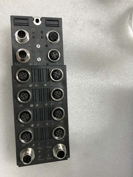
- Port Count: 8 digital inputs (single group)
- Input Type: 24VDC negative logic (sinking)
- Input Current: 7mA per point typical
- Input Voltage Range: 0–30VDC
- Operating Temperature: 0°C to +55°C
- Storage Temperature: -40°C to +85°C
- Relative Humidity: 5% to 95% (non-condensing)
- Protection Rating: IP67
- Mounting: DIN rail mounting
- Indicators: 1 green LED per input channel (ON when input activated)
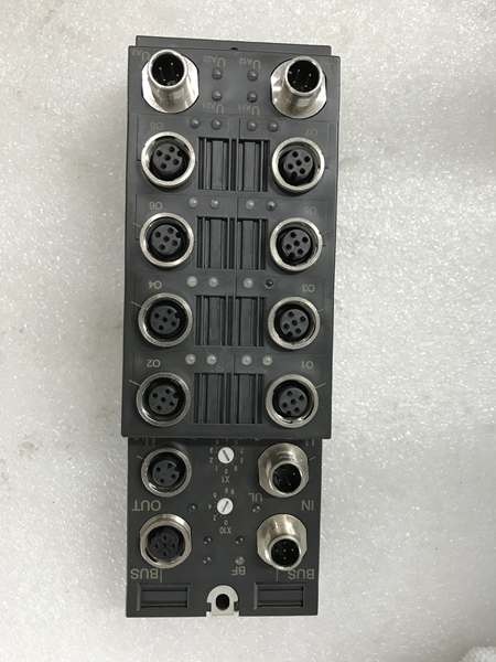
- Connection: M12 circular connectors (typically 4-pin per port)
- Power Consumption: Approximately 250mA at 24VDC
- Response Time: <5ms typical

GE IC676PBO082
The Real-World Problem It Solves
This module extends digital input monitoring directly into harsh industrial environments where standard I/O modules would fail. The IP67 rating eliminates the need for expensive enclosures in washdown areas, outdoor installations, and dusty manufacturing zones.
Where you’ll typically find it:
- Food and beverage processing: Monitoring sensors in washdown zones.
- Automotive manufacturing: Detecting part presence and position on assembly lines with high particulate exposure.
- Water treatment: Reading flow switches and level sensors in moist environments.
- Outdoor installations: Monitoring limit switches on outdoor conveyor systems and mobile equipment.
Bottom line: It brings distributed digital input monitoring to harsh environments without sacrificing reliability or response speed. The negative logic design matches common industrial sensor configurations.
Hardware Architecture & Under-the-Hood Logic
This is a Profibus-DP slave node designed for distributed I/O applications. It reads 24VDC input signals from field devices and transmits status to a Profibus master controller over the network.
-
Profibus Communication:
- Module connects to Profibus-DP network via 9-pin D-sub connector or M12 circular connector.
- Supports Profibus-DP V0 protocol with data exchange rates up to 12 Mbit/s.
- Node address configured via DIP switches or rotary selector.
- Data transmitted to master includes input status, diagnostic information, and module health.
-
Input Circuitry:
- Each of 8 channels monitors 24VDC input signals using negative logic (sinking) configuration.
- Internal optocouplers provide electrical isolation between field devices and internal electronics.
- Input filtering delays approximately 2-5ms to debounce mechanical switch contacts.
- Input current draw approximately 7mA per point when activated.
-
Environmental Protection:
- IP67-rated sealed housing prevents dust and water ingress.
- Gasketed M12 connectors maintain environmental seal when properly installed.
- Conformal coating on circuit boards protects against moisture and contaminants.
-
Diagnostics:
- Individual LEDs provide visual indication of input status (ON when active).
- Diagnostic bytes transmitted via Profibus report channel faults, wire breaks, and module health.
- Self-test functionality monitors internal electronics at startup.

GE IC676PBO082
Field Service Pitfalls: What Rookies Get Wrong
Miswiring negative logic inputs
Rookies wire sensors expecting sourcing (positive logic) behavior, connecting +24V to the input terminal and 0V to the return. This module uses negative logic—input activates when 0V is applied, and return expects +24V.
- Field Rule: Connect sensor common to +24VDC supply, and sensor output to the module input terminal. When sensor switches, it pulls the input to 0V, activating the channel.
Compromising IP67 with improper connector installation
While the module itself is IP67-rated, rookies use unsealed M12 connectors or fail to tighten connectors to specified torque, allowing water and dust ingress.
- Field Rule: Use only IP67-rated M12 connectors with proper gaskets. Tighten connectors to 0.5–0.8 Nm torque. Always install protective dust caps on unused ports.
Overlooking Profibus termination
Profibus networks require 220Ω termination resistors at both ends of the segment. Rookies omit termination or install it at the wrong node, causing intermittent communication failures.
- Field Rule: Install 220Ω termination resistors at the first and last nodes on the Profibus segment. Verify network signal quality with a Profibus bus monitor.
Exceeding operating temperature limits
The module operates 0°C to +55°C. Rookies install it in outdoor enclosures exposed to sub-freezing temperatures or direct sunlight exceeding the upper limit, causing communication dropouts.
- Field Rule: Ensure installation environment stays within the 0–55°C range. Use enclosure heating or cooling if ambient temperatures fall outside this specification.
Ignoring input filter delays
The module has a 2-5ms input filter for debouncing. Rookies expect sub-millisecond response times for high-speed counting applications, resulting in missed pulses.
- Field Rule: For high-speed applications requiring <1ms response, consider using dedicated high-speed counter modules or software input filters with faster response times.
Failing to configure correct baud rate
The module supports up to 12 Mbit/s, but must match the Profibus master’s baud rate. Rookies set the master to 1.5 Mbit/s but leave the module at default 9.6 Kbit/s, causing no communication.
- Field Rule: Verify baud rate settings match across all Profibus devices before commissioning. Use the module’s DIP switches or configuration tool to set the correct speed.
Commercial Availability & Pricing Note
Please note: The listed price is for reference only and is not binding. Final pricing and terms are subject to negotiation based on current market conditions and availability.


