
Description
Hard-Numbers: Technical Specifications
- Protocol Support: Profibus-DP (DP-V0, DP-V1)
- Profibus Speeds: 9.6, 19.2, 93.75, 187.5, 500, 1500 Kbits; 3, 6, 12 Mbits
- Port Count:
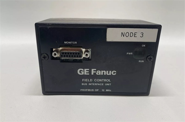
- Profibus Network: 1 × 9-pin D-sub connector
- Programmer Port: 1 × 9-pin D-sub connector (Hand-Held Programmer, HHP)
- Addressing: 8 DIP switches for node address configuration (00-127 range)
- I/O Module Capacity: Up to 8 Field Control I/O modules per BIU
- Max Nodes per Segment: 32 Profibus stations
- Profibus Topology: Linear bus (daisy-chain) with termination resistors at first and last nodes
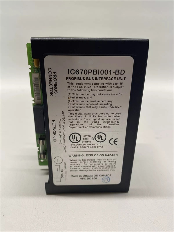
- Rated Input Voltage: 24 VDC
- Operating Voltage Range: 18–30 VDC
- Input Power: 7.7 W maximum
- Power Dissipation: 4.45 W
- Holdup Time: 10 ms maximum
- Network Medium: Shielded twisted pair (Belden #9463 or equivalent)
- Status LEDs: PWR, RUN, OK
- Operating Temperature: 0–55°C (32–131°F)
- Storage Temperature: -40–85°C
- MTBF: 180,000 hours
- Mounting: DIN rail or panel mount via Bus Interface Unit terminal block

GE IC670PBI001-DG
The Real-World Problem It Solves
This module eliminates proprietary cabling between distributed I/O racks and the main PLC. By bridging standard Profibus-DP to GE’s Field Control family, it gives you the flexibility to place I/O close to field devices while using open, widely-supported network infrastructure.
Where you’ll typically find it:
- Distributed I/O stations: Controlling remote sensor/actuator islands in packaging lines or material handling.
- Retrofit projects: Adding modern I/O to legacy GE PLCs via Profibus without proprietary bus hardware.
- Mixed-vendor systems: Integrating GE Field Control I/O with Siemens, Allen-Bradley, or other Profibus-capable PLCs.
Bottom line: It’s the gateway that converts a proprietary I/O family into an open standard—critical for distributed control architecture.
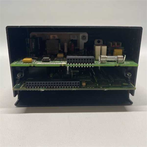
Hardware Architecture & Under-the-Hood Logic
The BIU is the brains of a Field Control station. It scans attached I/O modules, maps their data to Profibus protocol, and exchanges messages with the network master (PLC). All intelligence resides here; attached I/O modules are “dumb” execution devices.
-
Power-up:
- External 24VDC powers the BIU through the Bus Interface Unit terminal block.
- PWR LED illuminates when input voltage is within 18–30VDC range.
- BIU performs self-diagnostics and initializes communication circuits.
-
I/O Scanning:
- BIU scans all attached I/O modules (up to 8) via internal backplane.
- Reads input status, writes output commands, performs diagnostic checks.
- Configuration (I/O defaults, analog scaling, fault reporting) is stored locally.
-
Profibus Communication:
- Data is formatted into Profibus-DP frames and transmitted via 9-pin D-sub port.
- Node address is set via 8 DIP switches—must match master configuration.
- Speed is selectable via DIP switches or HHP (9.6K to 12M).
-
Programmer Port:
- Separate 9-pin D-sub port connects Hand-Held Programmer.
- Allows offline configuration, diagnostics, and firmware updates without disturbing network.
-
Diagnostics:
- RUN LED indicates active Profibus communication with master.
- OK LED indicates BIU and attached I/O modules have no faults.
- Fault codes are reported to master via Profibus and can be read via HHP.

GE IC670PBI001-DG
Field Service Pitfalls: What Rookies Get Wrong
Mismatching node address and DIP switch settings
Rookies configure the address in the PLC software but forget to set the matching DIP switches on the BIU. The module appears offline because the physical address doesn’t match the master’s table.
- Field Rule: Always verify DIP switch settings (00-127) against the Profibus master configuration table. Power-cycle the BIU after changing DIP switches.
Incorrect bus termination
Profibus requires termination resistors (typically 220Ω) at the first and last nodes only. Rookies terminate every node or omit termination entirely, causing signal reflections and communication errors.
- Field Rule: Enable termination on the first and last BIU in the segment. Disable termination on intermediate nodes.
Exceeding 32 nodes per segment
The Profibus DP standard limits each segment to 32 stations. Rookies stack additional nodes beyond this limit, causing random dropouts and unstable communication.
- Field Rule: Count all nodes (master, repeaters, BIUs, slaves). If exceeding 32, add repeaters to split segments.
Shielding and grounding errors
Profibus uses shielded twisted pair for noise immunity. Rookies ground both ends of the shield, creating ground loops that induce interference and cause communication failures.
- Field Rule: Ground the shield at the master end only. Leave the far end floating or connected via capacitor.
Ignoring holdup time during power loss
The BIU has 10 ms holdup time—enough for brief power dips but not for prolonged outages. Rookies underestimate voltage sag during motor starts, causing the BIU to reset and drop communication.
- Field Rule: Ensure 24VDC supply is sized for inrush loads and maintains >18V during worst-case sags. Add bulk capacitance if needed.
Forgetting analog scaling and I/O defaults
The BIU supports analog scaling and configurable I/O defaults (safe state on fault). Rookies leave these at factory settings, resulting in wrong engineering units or unsafe outputs during fault conditions.
- Field Rule: Use Hand-Held Programmer or configuration software to set proper analog scaling (e.g., 4–20mA to 0–1000 psi) and safe output defaults.
Commercial Availability & Pricing Note
Please note: The listed price is for reference only and is not binding. Final pricing and terms are subject to negotiation based on current market conditions and availability.


