
Description
Hard-Numbers: Technical Specifications
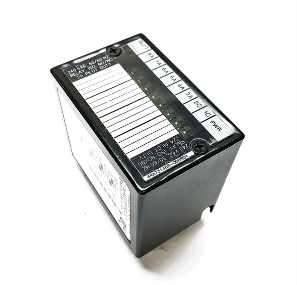
- Protocol Support: Genius Bus (IC670GBI002) / Profibus Interface Unit
- Port Count: 8 isolated relay outputs (6 Form A / 2 Form C)
- Rated Voltage: 5 VDC / 24 VDC / 125 VDC / 120 VAC / 240 VAC (nominal)
- Operating Voltage: 0–130 VDC; 0–265 VAC, 47–63 Hz
- Output Current:
- 2.0 A per point at 5–30 VDC (resistive)
- 2.0 A per point at 5–265 VAC (resistive)
- 0.2 A per point at 31–125 VDC (resistive)
- Maximum 16 A total per module (UL derating applies)
- Inrush Current: 5 A for 20 ms
- Minimum Load Current: 10 mA per point
- Switching Frequency: 20 cycles/minute maximum with inductive loads
- Response Time: 10 ms typical (ON/OFF)
- Contact Type: Silver alloy, fixed coil, moving armature
- Contact Resistance: 0.2 ohms at 1 A / 6 VDC
- Protection: RC snubber (47.5 ohms) across each output; no onboard fuses
- Power Draw from BIU: 313 mA maximum (all outputs on)
- Isolation Rating: 250 VAC continuous / 1500 VAC for 1 minute (field to backplane, group to group)
- Contact Life: Mechanical: 20,000,000 operations; Electrical: 100,000 operations at rated resistive load
- Wire Size: AWG #22–16 (two wires) or AWG #14 (one wire) per terminal; torque 9.6–11.5 in-lbs (1.1–1.3 Nm)

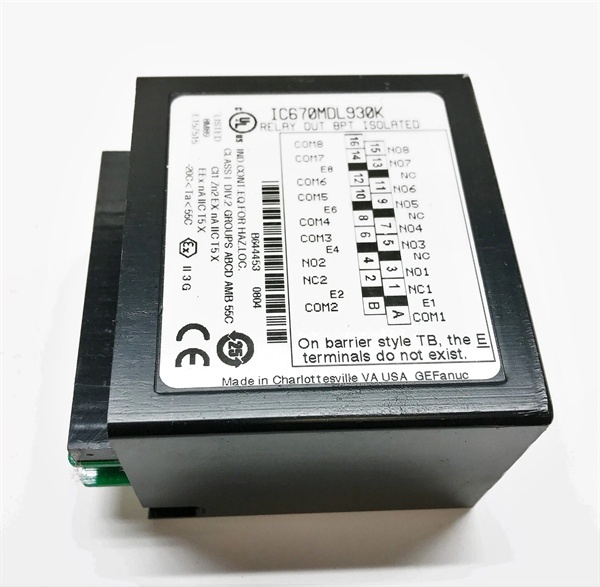
IC670MDL930K
The Real-World Problem It Solves
This module bridges mixed-voltage worlds—driving 120VAC contactors and 24VDC indicator stacks from the same rack—while providing galvanic isolation that protects control electronics from field surges.
Where you’ll typically find it:
- Motor control panels: Energizing 120VAC or 240VAC motor starters and contactors.
- Mixed-voltage control circuits: Switching 24VDC pilot lights alongside 120VAC solenoid valves.
- Isolation islands: Creating voltage boundaries between control logic (24VDC) and field power (120/240VAC).
Bottom line: It trades switching speed and density for isolation and contact flexibility. Use it where voltage diversity matters more than point count.
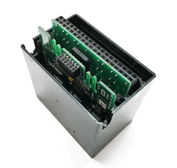
Hardware Architecture & Under-the-Hood Logic
This is a “dumb” relay card—no onboard processor. The Bus Interface Unit (BIU) handles all intelligence and supplies module logic power. Field power (AC or DC) comes from external sources switched by the relay contacts.
- The BIU sends 8 bits of discrete output data to the module over the backplane.
- Serial-to-parallel logic (handled by BIU) drives relay coils based on command states.
- Each relay is individually isolated:
- Form A (N.O.): Common and N.O. terminals only.
- Form C (N.O./N.C.): Common, N.O., and N.C. terminals.
- An RC snubber (47.5 ohms) across each contact suppresses high-frequency transients.
- No fuses—external protection is required for field loads.
- Silver alloy contacts provide low resistance (0.2 ohms) but degrade with inductive switching arcs.
- Individual LEDs show coil state (logical command), not actual contact closure—critical distinction for fault diagnosis.

IC670MDL930K
Field Service Pitfalls: What Rookies Get Wrong
Exceeding 2A per-point rating while assuming “16A module total”
The 16A module rating is a UL derating limit—it’s not a license to load any single channel to 16A. Each point maxes at 2A resistive (0.2A at 31–125VDC). Rookies see the “16A module” spec and attempt to drive 10A motors directly through one contact.
- Field Rule: Load current per point ≤2A (resistive) or ≤0.2A (31–125VDC). Use interposing contactors for higher currents.
Ignoring contact wear with inductive loads
Inductive loads (solenoids, contactors) cause contact arcing, reducing electrical life from 100,000 operations to as low as 50,000–200,000 cycles. Rookies replace failed modules but don’t add suppression to the load.
- Quick Fix: Install MOVs or RC snubbers across inductive loads. Contact life drops exponentially without suppression.
Misreading LEDs—coil state vs. contact closure
Each LED shows that the module is driving the relay coil, not that the contact actually closed. If the relay welds or the field circuit opens, the LED stays on but the load won’t switch. Rookies chase the field wiring when the relay itself has failed.
- Field Rule: Verify contact continuity at the terminal block with a multimeter if the LED is on but the load doesn’t energize.
Overloading the BIU power supply
This module draws 313 mA from the BIU—significantly more than output cards (typically 111 mA). Rookies stack multiple MDL930s without checking BIU power budget.
- Field Rule: Each MDL930 consumes 313 mA at 5V. Verify BIU power supply rating and derate for the total number of relay modules in the rack.
Missing external protection—no onboard fuses
This module has zero fusing. Shorted loads or wiring faults will weld contacts or damage field equipment. Rookies assume “protection included” until a fault burns through a terminal block.
- Field Rule: Install external fuses or circuit breakers for each output based on load current. Never rely on the module alone for overcurrent protection.
Commercial Availability & Pricing Note
Please note: The listed price is for reference only and is not binding. Final pricing and terms are subject to negotiation based on current market conditions and availability.


