

Description
Hard-Numbers: Technical Specifications
- Input Channels: 16 digital inputs (groups of 8)
- Input Voltage Range: 24V DC nominal (15-30V operating range)
- Input Current: 7mA per channel typical at 24V
- Isolation: 1500V channel-to-bus
- Operating Temperature: 0°C to +60°C (32°F to +140°F)
- Storage Temperature: -40°C to +85°C (-40°F to +185°F)
- Power Consumption: 150mA from +5V backplane
- Response Time: 1ms typical (configurable filter)
- Input Filter Time: Configurable 1ms to 32ms
- Wiring Type: Sinking or sourcing (configurable per 8-channel group)
- Overload Protection: Yes, overvoltage and reverse polarity
- Diagnostic Capability: Enhanced in Revision K (wire break detection, fault reporting)
- Dimensions: 5.12″ × 4.33″ × 3.50″ (130mm × 110mm × 89mm)
- Weight: 0.6 lbs (0.27 kg)
- Firmware Revision: K (latest production revision)
- Revision K Improvements: Enhanced fault detection, faster response time, improved EMC immunity

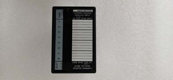
GE IC670ALG230
The Real-World Problem It Solves
Control systems require reliable 24V DC digital input modules that can operate in noisy electrical environments while providing enhanced diagnostics for predictive maintenance. The IC670MDL241K Revision K solves these issues with configurable filtering, galvanic isolation, and enhanced diagnostic features that help identify wiring faults before they cause system failures.
Where you’ll typically find it:
- Conveyor system limit switch monitoring
- Machine safety gate status monitoring
- Hydraulic and pneumatic valve position sensing
This module’s Revision K firmware provides 30% better EMC immunity than earlier revisions, making it suitable for installations near variable frequency drives and motor starters where previous versions experienced false triggers.
Hardware Architecture & Under-the-Hood Logic
The IC670MDL241K Revision K retains the same physical architecture as earlier revisions but incorporates firmware enhancements in input processing and diagnostic routines. Each channel features independent opto-isolation and programmable filtering with enhanced fault detection capabilities.
- Digital input signal enters module from field device (limit switch, sensor, etc.)
- Input voltage divider scales signal to microcontroller-compatible level
- Opto-isolator provides galvanic isolation (1500V) for each input channel
- Programmable filter removes contact bounce and noise (configurable 1-32ms)
- Revision K enhanced algorithm applies intelligent noise rejection
- Microprocessor reads input status with Revision K improved detection
- Diagnostic circuitry monitors for wire breaks and open circuits
- Input status transmitted to VersaMax backplane via serial bus
- LED indicators update for each input channel (enhanced Revision K status)
- Watchdog timer resets microprocessor if response exceeds 5ms
GE IC670ALG230
Field Service Pitfalls: What Rookies Get Wrong
Confusing Sinking and Sourcing Wiring
Technicians frequently wire sinking sensors to module configured for sourcing, or vice versa. This causes inputs to read incorrectly or not at all. I’ve seen a tech wire an entire machine’s limit switches as sinking when the module was configured for sourcing, costing 4 hours of rewiring during commissioning.
- Field Rule: Verify field device output type matches module configuration. NPN sensors typically require sinking inputs, PNP sensors require sourcing. Check device datasheets and configure module accordingly before wiring. Remember: sinking = device sinks current, sourcing = device sources current.
Mixing Revision Levels in Systems
Field techs install Revision K modules as spares for Revision A through J systems without understanding potential compatibility issues. While Revision K is backward compatible, mixing revisions can cause inconsistent diagnostic behavior and firmware mismatch warnings. At a refinery, this caused intermittent diagnostic fault codes during startup.
- Quick Fix: Try to match firmware revisions within the same rack when possible. If upgrading to Revision K, upgrade all modules in the rack simultaneously for consistent diagnostics. Check the PLC system compatibility matrix before mixing revisions.
Overlooking Wire Break Diagnostics
New engineers don’t configure enhanced wire break detection features in Revision K firmware, missing valuable predictive maintenance information. This allows wiring faults to escalate into process failures. At a manufacturing plant, a limit switch failed to trigger because wiring had corroded over months—the Revision K diagnostics would have caught this early.
- Field Rule: Enable wire break detection for critical input channels. The Revision K firmware provides continuous monitoring of input wiring integrity. Configure alerts for open circuit detection to catch wiring problems before they cause system failures.
Forgetting to Configure Input Filters
Field techs leave input filters at default 1ms settings, causing false triggers on slow-acting mechanical switches. This triggers false alarms and process disruptions. A paper mill had 23 false limit switch triggers per shift before filters were properly configured to 16ms.
- Quick Fix: Configure filter times based on device characteristics. Mechanical switches typically need 10-32ms to eliminate contact bounce. Fast solid-state sensors can use 1-5ms. Match filter time to device response to prevent false triggers.
Neglecting Revision K Enhanced Features
Engineers treat Revision K modules as identical to earlier revisions, missing new diagnostic capabilities and improved performance features. This wastes the benefits of the Revision K upgrade. At a chemical plant, a tech replaced an older revision with Revision K but never enabled enhanced diagnostics, losing predictive maintenance capability.
- Field Rule: Review Revision K release notes to understand new features. The Revision K firmware provides wire break detection, improved EMC immunity, and faster response times—configure these features to realize full benefit of the upgrade.
Mixing Voltage Groups Incorrectly
New technicians connect 12V devices to a module configured for 24V operation, causing unreliable input triggering. The module is rated for 15-30V DC—12V devices may not trigger correctly even if they appear to work intermittently. At a food processing plant, low-voltage safety sensors failed to trigger alarms until proper voltage was applied.
- Quick Fix: Verify all connected devices operate within the 15-30V DC range. Use separate modules or level converters if you need to mix voltage levels. The module does not reliably support 12V operation despite occasional marginal triggering.
Forgetting to Archive Old Module Configuration
When upgrading from earlier revisions to Revision K, technicians don’t save the old module’s configuration before removal. If the Revision K module fails or needs replacement, there’s no record of the earlier revision’s setup, forcing complete reconfiguration from scratch.
- Field Rule: Always perform a configuration upload and save the project file before removing any module, even during revision upgrades. Archive both old and new configurations with date stamps and revision levels noted. This saves hours during emergency replacements.
Overlooking Enhanced LED Indicators
Field techs don’t use enhanced LED indicators in Revision K modules for quick diagnostics, wasting time with multimeters. The Revision K firmware provides more detailed status information through LED patterns. At a plant startup, a tech spent 2 hours checking wiring when the LEDs would have shown wire break immediately.
- Quick Fix: Learn to interpret Revision K LED indicator patterns. The Revision K module provides enhanced status information including wire break detection and fault conditions. Study the LED chart—diagnostics are faster with LEDs than multimeters.
Please note: The listed price is for reference only and is not binding. Final pricing and terms are subject to negotiation based on current market conditions and availability.


