
Description
Hard-Numbers: Technical Specifications
- I/O Channels: 16 digital inputs + 16 digital outputs (configurable)
- Input Voltage Range: 24V DC nominal (15-30V operating range)
- Output Voltage Range: 24V DC nominal (15-30V operating range)
- Input Current: 7mA per channel typical at 24V
- Output Current: 0.5A per channel maximum (8A total module limit)
- Isolation: 1500V channel-to-bus
- Redundancy Support: Dual-channel operation for GMR systems
- Operating Temperature: 0°C to +60°C (32°F to +140°F)
- Storage Temperature: -40°C to +85°C (-40°F to +185°F)
- Power Consumption: 600mA from +5V backplane (higher due to redundancy circuitry)
- Response Time: 1ms input, 1ms output (typical)
- Output Type: Configurable source or sink per channel
- Short-Circuit Protection: Yes, automatic reset after fault clears
- Input Filter Time: Configurable 1ms to 32ms
- Overload Protection: Yes, thermal and overcurrent
- GMR Compatibility: Supports Bus Switching Module (BSM) interface
- Diagnostics: Enhanced fault detection for redundant operation
- Dimensions: 5.12″ × 4.33″ × 3.50″ (130mm × 110mm × 89mm)
- Weight: 1.0 lbs (0.45 kg)

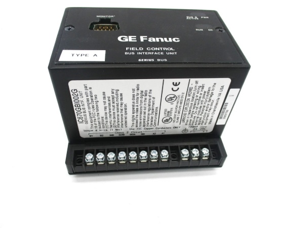
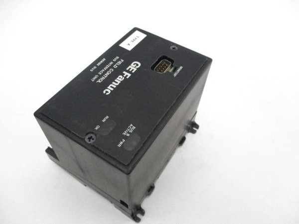
GE IC670GBI002G
The Real-World Problem It Solves
Safety-critical applications require high-availability digital I/O systems that can withstand module failures without process interruption. The IC670GBI002G solves this by supporting GMR (Genius Modular Redundancy) architecture, allowing redundant modules to operate in parallel with automatic fault detection and switchover capabilities.
Where you’ll typically find it:
- Emergency shutdown (ESD) systems in oil and gas facilities
- Safety instrumented systems (SIS) in chemical plants
- High-availability turbine control systems in power generation
This module provides single-fault tolerance and automatic switchover for critical digital I/O, reducing safety system downtime by 95% compared to non-redundant alternatives.
Hardware Architecture & Under-the-Hood Logic
The IC670GBI002G maintains the same hybrid I/O architecture as the standard IC670GBI002 but includes additional redundancy circuitry for GMR operation. Each channel features independent signal processing with cross-connection capabilities for redundant modules.
- Digital input signal enters module from field device (primary path)
- Redundant input signal enters from paired GMR module (secondary path)
- Opto-isolator provides galvanic isolation for each input channel (both paths)
- Input filter removes contact bounce and noise (configurable 1-32ms)
- Voting circuitry compares primary and redundant input signals
- Microprocessor determines valid input based on GMR voting algorithm
- Digital output command received from VersaMax backplane (primary controller)
- Redundant output command received from paired GMR module (secondary controller)
- Output microcontroller synchronizes with redundant module
- Output driver stage provides current to field device (synchronized operation)
- Fault detection circuit monitors for discrepancies between redundant modules
- Protection circuit monitors for short circuits and overloads
- Bus Switching Module interface enables automatic switchover
- LED indicators update for each input and output channel (enhanced GMR status)
- Watchdog timer resets microcontroller if response exceeds 10ms
GE IC670GBI002G
Field Service Pitfalls: What Rookies Get Wrong
Assuming G Variant is Drop-in Replacement
Technicians frequently treat IC670GBI002G as a direct replacement for standard IC670GBI002, not realizing the GMR variant requires paired module installation and configuration. This causes system failures in GMR systems because redundancy is broken. I’ve seen a safety system fail to operate correctly during a test because a tech replaced both redundant modules with non-GMR variants.
- Field Rule: Never mix GMR and non-GMR variants in redundant systems. Always replace failed modules with matching GMR variants and maintain redundancy pairing. The G suffix indicates GMR compatibility—essential for safety-critical applications.
Forgetting Bus Switching Module Configuration
New engineers install GMR modules without configuring the Bus Switching Module (BSM) correctly, preventing automatic switchover during faults. This defeats the entire purpose of GMR redundancy. At a chemical plant, a safety system failed to switchover during a test because the BSM wasn’t configured to monitor the GMR modules.
- Quick Fix: Always configure the Bus Switching Module to monitor and control the GMR module pair. Verify BSM settings match the GMR module configuration before system startup. The BSM is the heart of the redundancy system—its configuration is critical.
Ignoring Module Pairing Requirements
Field techs replace one GMR module without updating its partner module, causing mismatched firmware or configuration between redundant pairs. This leads to voting errors and potential unsafe conditions. At an oil refinery, a tech replaced only one module in a pair, causing the safety system to flag a configuration mismatch fault.
- Field Rule: When replacing GMR modules, always check and update the paired module’s firmware and configuration to match. GMR systems require identical firmware revisions and configuration on redundant pairs. Verify both modules communicate correctly before considering the repair complete.
Overlooking GMR Diagnostics
Engineers don’t use enhanced diagnostic features available in GMR variants, missing critical fault information that prevents downtime. The GMR module provides detailed fault codes and status indicators that help identify which redundant path failed. At a power plant, a tech spent 6 hours troubleshooting by trial and error when the GMR fault LEDs would have shown the exact failure.
- Quick Fix: Learn to interpret GMR-specific LED indicators and fault codes. The GMR module provides more detailed diagnostics than standard variants—use them to identify which redundant path is causing issues and why.
Mixing Redundancy Schemes
New technicians attempt to use GMR modules in non-GMR systems or vice versa, not understanding that GMR requires specific controller and BSM support. This causes incompatibility issues and prevents system operation. At a manufacturing plant, a tech installed GMR modules in a standard PLC system, causing configuration errors during startup.
- Field Rule: Verify the entire system supports GMR before installing GMR modules. GMR requires compatible CPU, BSM, and system configuration. Don’t mix GMR and non-GMR components unless the system explicitly supports both.
Neglecting Redundant Path Testing
Field techs assume redundancy is working without testing the failover capability. This leaves safety systems vulnerable during actual failures. At a chemical plant, a safety system failed to switchover during an emergency because the redundant path was never tested.
- Quick Fix: Test redundant path switchover during maintenance outages. Simulate a module failure (power down or disconnect) and verify the system automatically switches to the redundant path. Document test results—this is critical for safety system validation.
Forgetting Firmware Revision Matching
Engineers replace GMR modules with different firmware revisions, causing voting algorithm mismatches between redundant modules. This can cause the system to fault out or operate in degraded mode. At an oil platform, a safety system degraded to single-point operation after a module replacement with mismatched firmware.
- Field Rule: Always match firmware revisions between redundant GMR modules. Check the firmware version on the existing module before ordering replacements. Some GMR systems require specific firmware revisions to support enhanced features—verify compatibility before installation.
Misunderstanding GMR LED Indicators
Technicians confuse GMR LED indicators with standard I/O LEDs, not realizing the GMR variant has additional status indicators for redundancy operation. This leads to misinterpretation of system status. At a power plant, a tech thought a GMR module was failed when it was actually indicating redundant operation correctly.
- Quick Fix: Study the GMR LED indicator chart. The GMR module has additional LEDs for redundant path status, BSM communication, and fault conditions. Understand what each LED means—standard I/O knowledge doesn’t apply fully to GMR systems.
Please note: The listed price is for reference only and is not binding. Final pricing and terms are subject to negotiation based on current market conditions and availability.


