
Description
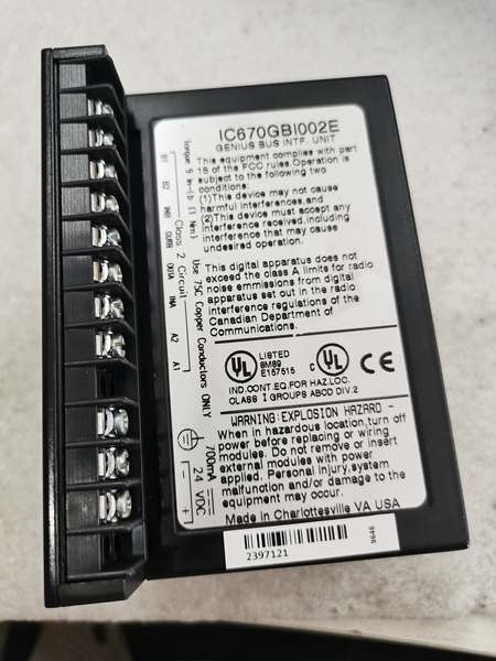
Hard-Numbers: Technical Specifications
- I/O Channels: 16 digital inputs + 16 digital outputs (configurable)
- Input Voltage Range: 24V DC nominal (15-30V operating range)
- Output Voltage Range: 24V DC nominal (15-30V operating range)
- Input Current: 7mA per channel typical at 24V
- Output Current: 0.5A per channel maximum (8A total module limit)
- Isolation: 1500V channel-to-bus
- Operating Temperature: 0°C to +60°C (32°F to +140°F)
- Storage Temperature: -40°C to +85°C (-40°F to +185°F)
- Power Consumption: 550mA from +5V backplane
- Response Time: 1ms input, 1ms output (typical)
- Output Type: Configurable source or sink per channel
- Short-Circuit Protection: Yes, automatic reset after fault clears
- Input Filter Time: Configurable 1ms to 32ms
- Overload Protection: Yes, thermal and overcurrent
- Dimensions: 5.12″ × 4.33″ × 3.50″ (130mm × 110mm × 89mm)
- Weight: 0.9 lbs (0.41 kg)

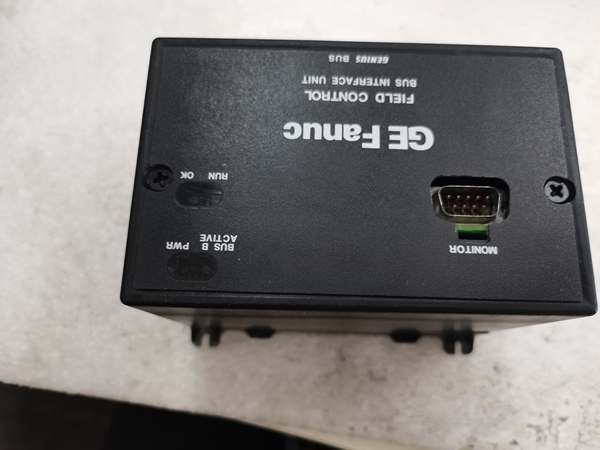
GE IC670GBI002
The Real-World Problem It Solves
Control systems waste cabinet space by using separate input and output modules for mixed digital I/O applications. The IC670GBI002 eliminates this by providing 16 inputs and 16 outputs in a single module, reducing panel space requirements by 50% while maintaining the same performance characteristics as dedicated modules.
Where you’ll typically find it:
- Control cabinet door interface stations
- Machine center local control panels
- Conveyor system junction boxes
This hybrid configuration reduces installation costs by 40% and simplifies wiring in applications where inputs and outputs are grouped together, such as local operator stations and equipment interface panels.
Hardware Architecture & Under-the-Hood Logic
The IC670GBI002 is a hybrid digital I/O module with independent input and output circuitry. Each input channel features opto-isolation and programmable filtering, while output channels provide configurable source/sink operation with built-in protection.
- Digital input signal enters module from field device (limit switch, sensor, etc.)
- Opto-isolator provides galvanic isolation (1500V) for each input channel
- Input filter removes contact bounce and noise (configurable 1-32ms)
- Microprocessor reads input status and updates internal image
- Digital output command received from VersaMax backplane
- Output microcontroller determines source or sink operation mode
- Output driver stage provides current to field device (source) or sinks current (sink)
- Protection circuit monitors for short circuits and overloads
- Output status transmitted back to backplane for verification
- LED indicators update for each input and output channel
- Watchdog timer resets microcontroller if response exceeds 10ms

GE IC670GBI002
Field Service Pitfalls: What Rookies Get Wrong
Confusing Source and Sink Wiring
Technicians frequently wire sinking inputs to sourcing outputs or vice versa without configuring the module properly. This causes inputs to read incorrectly or outputs to not drive loads. I’ve seen a tech spend 3 hours troubleshooting a control panel before discovering 8 of 16 outputs were wired for the wrong operation mode.
- Field Rule: Verify field device wiring requirements match module configuration. NPN sensors typically require sinking inputs, PNP sensors require sourcing. Check device datasheets and configure module accordingly before wiring.
Exceeding Module Current Limits
New engineers don’t calculate total module current draw, exceeding the 8A total limit when multiple outputs drive high-current loads simultaneously. This causes the module to shut down and can damage output drivers. At a manufacturing plant, a tech drove 16 0.5A loads simultaneously, tripping the module’s protection.
- Quick Fix: Calculate total output current before installation. Never exceed 8A total module current even if individual channels are within 0.5A limit. Use multiple modules or external relays for higher current applications.
Forgetting Input Filter Configuration
Field techs leave input filters at default 1ms settings, causing false triggers on slow-acting mechanical switches. This triggers false alarms and process disruptions. A food processing plant had 17 false limit switch triggers per shift before filters were properly configured.
- Field Rule: Configure filter times based on device characteristics. Mechanical switches typically need 10-32ms to eliminate contact bounce. Fast sensors can use 1-5ms. Match filter time to device response to prevent false triggers.
Ignoring Output Short-Circuit Protection
Technicians replace modules immediately after a short circuit causes a channel fault, not realizing the protection circuit automatically resets when the fault clears. At a refinery, a tech replaced two modules before discovering the short was in the field wiring and would have cleared if they’d waited 10 seconds.
- Field Rule: When an output fault LED activates, first disconnect the field wiring and measure for shorts. If the field device is shorted, fix it first. The module will automatically reset once power is cycled or the fault condition clears after approximately 10 seconds.
Mixing Voltage Levels on Same Module
Engineers connect 12V devices and 24V devices to the same module without considering the voltage range limitations. The module is rated for 15-30V DC—12V devices may not trigger inputs correctly, and 24V devices on 12V outputs won’t function.
- Quick Fix: Verify all connected devices operate within the 15-30V DC range. Use separate modules or level converters if you need to mix voltage levels. The module does not support mixed voltage operation.
Overlooking Ground Reference Matching
New engineers connect input commons and output commons to different ground references, creating ground loop currents that cause erratic behavior. This is particularly problematic when inputs and outputs connect to equipment with different ground potentials.
- Field Rule: Connect all input and output commons to the same ground reference point in the cabinet. Use star grounding topology to prevent ground loops. Avoid mixing ground references from different power sources on the same module.
Neglecting LED Diagnostics
Field techs don’t use the LED indicators to quickly identify failed channels, wasting time with multimeters. Each input and output has its own LED that provides immediate status indication. At a plant startup, a tech spent 2 hours checking wiring with a multimeter when the LEDs would have shown the problem immediately.
- Quick Fix: Use the LED indicators first when troubleshooting. Inputs: LED ON = active signal present. Outputs: LED ON = output is driven. LED OFF = input inactive or output not driven. LED flashing = fault condition on that channel.
Improper Wire Gauge Selection
Engineers use undersized wire for high-current output applications, causing voltage drop and overheating. The module supports up to 0.5A per channel—using AWG #22 wire causes problems at 0.3A loads.
- Field Rule: Use minimum AWG #18 wire for outputs carrying 0.3-0.5A. For lower currents, AWG #20-22 is acceptable. Consider voltage drop over wire length—long runs require larger gauge to maintain 24V at the load.
Please note: The listed price is for reference only and is not binding. Final pricing and terms are subject to negotiation based on current market conditions and availability.


