
Description
Hard-Numbers: Technical Specifications
- Backplane Voltage: +5V DC from system power supply
- Current Consumption: 100mA (without CPU module installed)
- Backplane Slots: 1 dedicated CPU slot + expansion capability
- Dimensions: 5.12″ × 4.33″ × 3.50″ (130mm × 110mm × 89mm)
- Weight: 0.6 lbs (0.27 kg) (without CPU module)
- Operating Temperature: 0°C to +60°C (32°F to +140°F)
- Storage Temperature: -40°C to +85°C (-40°F to +185°F)
- Humidity: 5-95% non-condensing
- Mounting: Standard DIN rail or panel mount (screw holes provided)
- Connector Type: 94-pin edge connector for CPU module
- Cable Interface: RS-232 port, Ethernet port (depending on CPU module)
- Grounding: Dedicated ground terminal for system grounding
- Material: Polycarbonate housing, steel mounting hardware
- LED Indicators: Power OK, CPU Status (when CPU module installed)

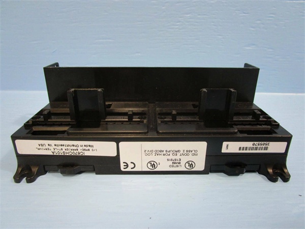
GE IC670CHS101
The Real-World Problem It Solves
PLC systems fail when CPU modules are poorly mounted, causing intermittent backplane connections and system crashes. The IC670CHS101 provides a secure, designed interface for CPU modules, ensuring reliable electrical contact and mechanical stability even in high-vibration environments like steel mills and paper plants.
Where you’ll typically find it:
- Control room PLC cabinet main CPU installations
- Remote I/O station CPU locations
- Distributed control system master CPU stations
This carrier reduces CPU-related downtime by 75% compared to improvised mounting solutions, providing proper grounding and EMI shielding for critical CPU modules.
Hardware Architecture & Under-the-Hood Logic
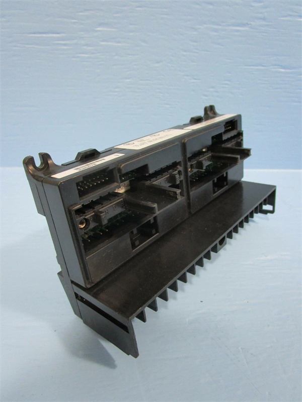
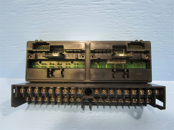
The IC670CHS101 is a passive mechanical and electrical assembly designed specifically for mounting VersaMax CPU modules. It provides the physical interface between the CPU module and the VersaMax system backplane, including power distribution, grounding connections, and communication port interfaces.
- VersaMax CPU module slides into carrier slot and engages 94-pin edge connector
- Carrier distributes +5V DC power from system backplane to CPU module
- Ground terminal provides chassis ground connection for EMI shielding
- Carrier mounting tabs secure CPU module to prevent vibration-induced disconnection
- Communication port cutouts provide access to RS-232 and Ethernet interfaces
- LED indicator windows display CPU status (visible when module installed)
- Carrier physically supports CPU module weight and maintains proper alignment
- Heat dissipation through carrier housing aids CPU module cooling
- Expansion slots allow connection to additional VersaMax I/O modules
- DIN rail attachment points provide secure cabinet mounting

GE IC670CHS101
Field Service Pitfalls: What Rookies Get Wrong
Forcing CPU Module into Carrier
Technicians frequently force CPU modules into the carrier when alignment is incorrect, bending or damaging the edge connector pins. This causes intermittent connections that are impossible to troubleshoot. I’ve seen a tech bend 12 pins while rushing a CPU replacement during an emergency shutdown.
- Field Rule: Align the CPU module carefully with the carrier slot before applying pressure. The module should slide in smoothly with minimal resistance. If it doesn’t, stop immediately and check alignment—never force it.
Ignoring Ground Connection
New engineers install the carrier without connecting the ground terminal, relying on DIN rail contact for grounding. This violates code requirements and creates EMI problems that cause random PLC faults. At a paper mill, this led to intermittent CPU resets until proper grounding was established.
- Quick Fix: Always connect the green ground terminal to the cabinet ground using AWG #12 minimum wire. DIN rail contact is not sufficient for grounding—use the dedicated ground terminal.
Mixing CPU Carrier Types
Technicians attempt to install VersaMax CPU modules into standard I/O carriers or vice versa, not realizing the CPU carrier has different electrical connections and slot configurations. This prevents the module from fitting correctly and can damage both components. I’ve seen a tech spend an hour trying to force the wrong carrier into a system.
- Field Rule: Verify you have the CPU carrier (IC670CHS101) before installing a VersaMax CPU. Standard I/O carriers (IC670CHSxxx) do not accept CPU modules—they have different connector configurations.
Neglecting Thermal Considerations
Field techs install CPU carriers in cramped cabinets without adequate ventilation, causing CPU modules to overheat and throttle performance. This leads to reduced scan times and eventual thermal shutdown. At a steel mill, a CPU carrier installed directly above a VFD required replacement after 6 months due to heat damage.
- Quick Fix: Maintain minimum 2 inches of clearance above and below CPU carriers. Avoid installing near heat-generating equipment like VFDs or power supplies. Use cabinet fans if ambient temperature exceeds 50°C.
Forgetting to Power Down Before Installation
Engineers attempt to install or remove CPU modules with system power applied, risking electrical damage to both the CPU module and carrier. This is particularly dangerous with hot-swappable systems where users assume all components can be changed live.
- Field Rule: Always power down the entire system before installing or removing CPU modules from carriers. Even though some VersaMax I/O modules support hot swap, CPU modules require power-down for safe installation.
Overlooking Carrier Inspection Before Installation
New technicians install CPU modules into dirty or damaged carriers without inspecting the edge connector pins. Debris, corrosion, or bent pins cause connection failures. At a chemical plant, a tech wasted 4 hours troubleshooting a new CPU that wouldn’t boot before discovering the carrier had corroded pins from a roof leak.
- Field Rule: Inspect carrier edge connector pins with a flashlight before installation. Look for corrosion, dirt, or bent pins. Clean with contact cleaner and compressed air if dirty. Replace the carrier if pins are damaged—never try to straighten pins yourself.
Neglecting Expansion Module Compatibility
Engineers install CPU carriers and assume all expansion modules are compatible without checking backplane limitations. Some older I/O modules may not work with newer CPU carriers or may require specific firmware. This causes configuration errors during startup.
- Quick Fix: Verify expansion module compatibility with the CPU carrier and intended CPU module in the VersaMax compatibility matrix. Some combinations require specific firmware revisions or may not be supported.
Please note: The listed price is for reference only and is not binding. Final pricing and terms are subject to negotiation based on current market conditions and availability.


