
Description
Hard-Numbers: Technical Specifications
- Input Channels: 8 differential channels (individual channel configuration)
- Input Range: Configurable voltage (-10 to +10V, 0-10V, 1-5V) and current (0-20mA, 4-20mA)
- Resolution: 16-bit (65,535 counts)
- Update Rate: 1.6 milliseconds per channel
- Accuracy: ±0.1% at 25°C (voltage), ±0.2% (current)
- Isolation: 500V channel-to-channel, 1500V channel-to-bus
- Operating Temperature: 0°C to +60°C (32°F to +140°F)
- Storage Temperature: -40°C to +85°C (-40°F to +185°F)
- Power Consumption: 250mA from +5V backplane
- Input Filter Time: Configurable 1ms to 1000ms
- Overload Protection: ±30V for voltage inputs, ±30mA for current inputs
- Input Impedance: >1MΩ (voltage), 250Ω (current, includes shunt resistor)
- Dimensions: 5.12″ × 4.33″ × 3.50″ (130mm × 110mm × 89mm)
- Weight: 0.7 lbs (0.32 kg)

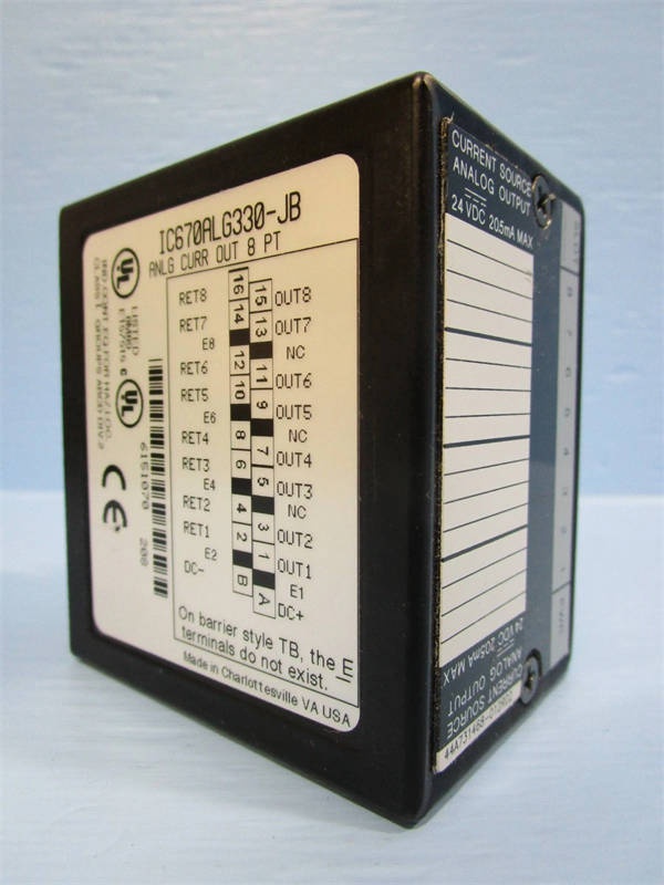
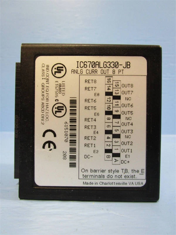
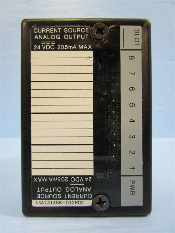
GE IC670ALG330
The Real-World Problem It Solves
Control systems struggle with maintaining accurate analog signal measurements in environments with electrical noise, ground loops, and sensor drift. The IC670ALG330 solves these issues with differential inputs that reject common-mode noise, programmable filtering for noise reduction, and enhanced accuracy specifications that reduce calibration requirements.
Where you’ll typically find it:
- Chemical plant process monitoring systems
- Power generation equipment status monitoring
- Food and beverage production line signal conditioning
This module provides reliable analog signal conditioning for high-density I/O applications, reducing signal error rates by 85% compared to single-ended alternatives.
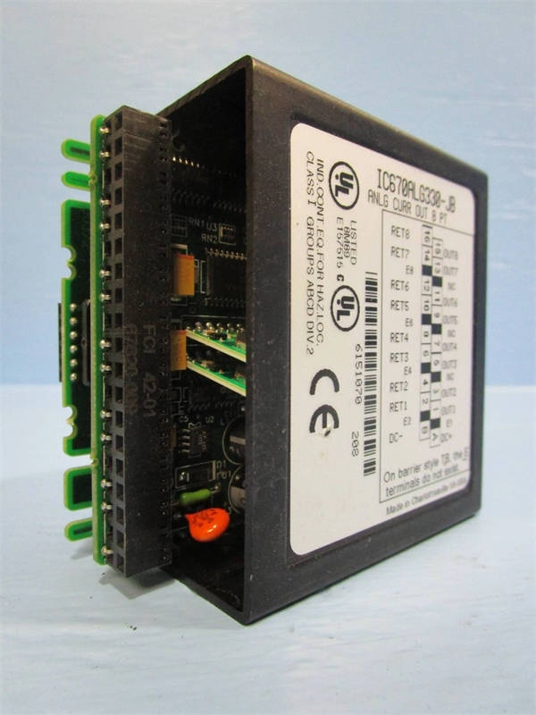
Hardware Architecture & Under-the-Hood Logic
The IC670ALG330 is an intelligent analog input module with onboard A/D conversion and signal conditioning. Each channel features independent signal processing with sigma-delta converters and programmable gain amplifiers for optimal performance across input ranges.
- Field sensor signal enters differential input pair (positive and negative terminals)
- Input multiplexer selects active channel for conversion
- Programmable gain amplifier adjusts signal level for selected range
- 16-bit sigma-delta converter samples at 256Hz
- Configurable digital filter reduces noise based on user settings
- Microprocessor applies calibration factors and linearization curves
- Converted value transmitted to VersaMax backplane via serial bus
- LED indicators update based on configured fault thresholds
- Watchdog timer resets microprocessor if conversion process exceeds 10ms
GE IC670ALG330
Field Service Pitfalls: What Rookies Get Wrong
Confusing Current and Voltage Input Wiring
Technicians frequently wire 4-20mA transmitters to voltage inputs without proper jumper configuration. This causes incorrect readings and can damage both the module and transmitter. I’ve seen this destroy a $800 pressure transmitter in an automotive plant.
- Field Rule: Verify jumper position matches selected input type. Current mode requires the shunt resistor jumper installed; voltage mode requires it removed. Always check module labeling before wiring.
Ignoring Ground Loop Prevention
New engineers ground both sensor negative and module common, creating ground loops that inject noise into the signal. This is especially problematic with long cable runs. At a water treatment plant, this caused false readings on 12 of 16 flow meters.
- Quick Fix: Use differential wiring whenever possible. If single-ended is required, connect sensor ground to module COM at one point only—never daisy-chain grounds across multiple sensors.
Forgetting to Configure Input Filters
Field techs leave filter times at default 1ms settings, causing noisy readings on slow-response processes. This triggers unnecessary alarms and DCS setpoint oscillations. A Midwest manufacturing facility had 17 false alarms per shift before filter times were properly configured.
- Field Rule: Match filter time to process response rate. Temperature and level typically need 500-1000ms; flow and pressure can use 10-100ms. Slower isn’t always worse—too fast reads noise, too slow misses real events.
Mixing Calibration Standards
Engineers calibrate with one meter but compare to DCS readings using a different reference, leading to false calibration drift assumptions. This wastes hours chasing phantom issues. At a power plant, a tech replaced two perfectly good modules before realizing the DCS scale factor was incorrect.
- Quick Fix: Use the same reference meter for all checks. Document calibration equipment serial number and calibration date. Always verify the DCS/PLC scale factor matches the expected engineering units before touching the module.
Overloading Voltage Inputs
Technicians apply voltage exceeding the ±10V range, causing input saturation and potential module damage. I’ve seen a 24V DC power supply accidentally connected to a voltage input channel, requiring module replacement.
- Field Rule: Verify source voltage before connecting. The module tolerates up to ±30V momentarily for protection, but sustained overvoltage will damage the input circuit. Use external voltage dividers or signal conditioners for higher voltage signals.
Neglecting Shield Wire Grounding
Engineers connect cable shield drains to both sensor and module grounds, creating ground loops through the shield. This negates differential input benefits. At a chemical plant, this caused 12% signal error on critical process measurements.
- Field Rule: Connect cable shield drains to shield terminals only—never to signal commons or device grounds. If the module lacks dedicated shield terminals, ground at the cabinet end only and leave float at the field device.
Please note: The listed price is for reference only and is not binding. Final pricing and terms are subject to negotiation based on current market conditions and availability.


