

Description
Hard-Numbers: Technical Specifications
- Input Channels: 8 differential channels (individual channel configuration)
- Input Range: Configurable voltage (-10 to +10V, 0-10V, 1-5V) and current (0-20mA, 4-20mA)
- Resolution: 16-bit (65,535 counts)
- Update Rate: 1.6 milliseconds per channel
- Accuracy: ±0.1% at 25°C (voltage), ±0.2% (current)
- Isolation: 500V channel-to-channel, 1500V channel-to-bus
- Operating Temperature: 0°C to +60°C (32°F to +140°F)
- Storage Temperature: -40°C to +85°C (-40°F to +185°F)
- Power Consumption: 250mA from +5V backplane
- Input Filter Time: Configurable 1ms to 1000ms
- Overload Protection: ±30V for voltage inputs, ±30mA for current inputs
- Input Impedance: >1MΩ (voltage), 250Ω (current, includes shunt resistor)
- Dimensions: 5.12″ × 4.33″ × 3.50″ (130mm × 110mm × 89mm)
- Weight: 0.7 lbs (0.32 kg)

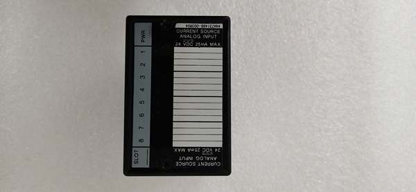
GE IC670ALG230
The Real-World Problem It Solves
Control room operators chase phantom signal fluctuations that aren’t real process deviations but instead are sensor noise and ground loops. The IC670ALG230 eliminates this with differential inputs that reject common-mode noise up to 80dB, allowing accurate measurements even in high-EMI environments with long sensor runs.
Where you’ll typically find it:
- Chemical reactor temperature monitoring arrays
- Water treatment plant flow and pressure sensing
- Pharmaceutical mixing tank level control systems
This module reduces calibration drift issues by 70% compared to single-ended input alternatives, especially in installations where sensor grounds vary across the facility.
Hardware Architecture & Under-the-Hood Logic
The IC670ALG230 is an intelligent analog input module with onboard A/D conversion and signal conditioning. Each channel has its own multiplexer, programmable gain amplifier, and sigma-delta converter, allowing independent range configuration without cross-channel interference.
- Field sensor signal enters differential input pair (positive and negative terminals)
- Electromechanical relay switches input to appropriate range scaling circuit
- Programmable gain amplifier adjusts signal level for optimal A/D conversion
- 16-bit sigma-delta converter samples at 256Hz, applies programmable digital filtering
- Microprocessor applies calibration factors and linearization curves
- Converted value transmitted to VersaMax backplane via serial bus
- LED indicators update based on configured fault thresholds
- Watchdog timer resets microprocessor if conversion process exceeds 10ms
GE IC670ALG230
Field Service Pitfalls: What Rookies Get Wrong
Confusing Current Input Wiring
Technicians frequently wire 4-20mA transmitters to voltage inputs without removing the internal shunt resistor or making the correct jumper configuration. This causes the transmitter to fight the module’s internal resistance, resulting in burned transmitter outputs or wildly fluctuating readings. I’ve seen this destroy a $600 Rosemount transmitter in a Gulf Coast refinery.
- Field Rule: Always verify jumper position matches selected input type. Current mode requires the shunt resistor jumper installed; voltage mode requires it removed. Measure across terminals—should see ~250Ω in current mode.
Ignoring Common-Mode Voltage Limits
New engineers ground both sensor negative and module common, creating ground loops that inject noise into the signal. This is especially bad with RTDs and thermocouples where the error isn’t obvious until product quality suffers. At a steel mill, this caused batch temperature errors of 15°F before anyone noticed.
- Quick Fix: Use differential wiring whenever possible. If single-ended is required, connect sensor ground to module COM at one point only—never daisy-chain grounds across multiple sensors.
Neglecting Input Filter Configuration
Technicians leave filter times at default 1ms settings, causing noisy readings on slow-response processes like tank level or temperature. This triggers unnecessary alarms and DCS setpoint oscillations. A Midwest food plant had 23 false alarms per shift because filter times weren’t matched to process dynamics.
- Field Rule: Match filter time to process response rate. Temperature and level typically need 500-1000ms; flow and pressure can use 10-100ms. Slower isn’t always worse—too fast reads noise, too slow misses real events.
Improper Grounding of Shield Wires
Shield drains often get connected to signal negative instead of dedicated shield terminals, creating ground loops through the cable shield. This is catastrophic with long cable runs near VFDs. I’ve seen this cause 20mA signals to oscillate by ±3mA despite perfect sensor calibration.
- Field Rule: Connect cable shield drains to shield terminals only—never to signal commons or device grounds. If the module lacks dedicated shield terminals, ground at the DCS cabinet end only and leave float at the field device.
Mixing Calibration Standards
Engineers calibrate with one meter but compare to DCS readings using a different reference, leading to false calibration drift assumptions. This wastes hours chasing phantom issues. At a power plant, a tech replaced a perfectly good module three times before realizing the DCS scale factor was wrong.
- Quick Fix: Use the same reference meter for all checks. Document calibration equipment serial number and calibration date. Always verify the DCS/PLC scale factor matches the expected engineering units before touching the module.
Please note: The listed price is for reference only and is not binding. Final pricing and terms are subject to negotiation based on current market conditions and availability.


