


Description
Hard-Numbers: Technical Specifications
- Input Voltage Range: 18-32VDC dual redundant inputs
- Output Voltage: 24VDC ±5% regulated
- Output Current: 5A continuous, 7A peak (10 seconds)
- Bus Termination: Built-in terminating resistors
- Operating Temperature: -40°C to +70°C (-40°F to +158°F)
- Isolation Rating: 1500V RMS input to output
- Power Factor: 0.98 at full load
- Hold-up Time: 50ms after primary input loss
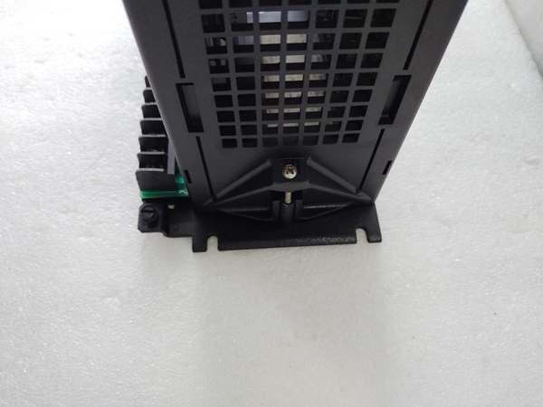
- Dimensions: 8.5″H x 4.5″W x 3.0″D
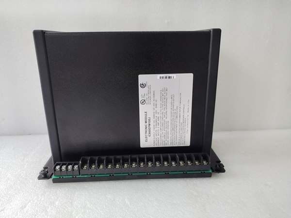
- LED Indicators: PWR1, PWR2, BUS, FAULT, OK
- Switchover Time: <1ms between redundant inputs

GE IC660EPM100J
The Real-World Problem It Solves
Nuclear power plants require uninterrupted power to safety instrumented systems, but primary power feeds can fail due to equipment damage or severe weather. The IC660EPM100J provides seamless automatic switchover between redundant power sources to maintain continuous operation of critical I/O blocks.
Where you’ll typically find it:
- Oil and gas offshore platform control systems
- Military radar and communication arrays
- Transportation tunnel ventilation control networks
This module eliminates single-point power failure points that could lead to catastrophic safety incidents in critical infrastructure.
Hardware Architecture & Under-the-Hood Logic
The IC660EPM100J serves as the primary power source and bus monitor for Genius I/O segments. It includes dual power supply circuits and an intelligent switchover controller that maintains continuous output even during input power transitions.
- Dual DC inputs pass through independent EMI filters and surge suppressors
- Switching regulators convert each input to regulated 24VDC
- Controller monitors input voltage and current from both sources
- Automatic switchover circuit selects primary power source, with <1ms transition time on failure
- Main output bus provides power to I/O blocks, with active current limiting
- Diagnostic data transmitted to PLC via Genius Bus interface

GE IC660EPM100J
Field Service Pitfalls: What Rookies Get Wrong
Mismatched Redundant Input VoltagesTechnicians connect 24VDC from different sources without verifying voltage levels. A 0.5V mismatch between inputs can cause constant micro-switching that wears out relay contacts within months.
- Field Rule: Use a precision voltmeter to ensure redundant input voltages differ by less than 0.2V RMS before connecting.
Incorrect Cable RoutingNew engineers run power cables and communication wires in the same conduit, creating electromagnetic interference (EMI) that disrupts bus communications. This can cause false fault codes and unexpected PLC behavior.
- Quick Fix: Route power cables in separate conduits at least 12 inches away from signal wiring to reduce EMI.
Overlooking Grounding RequirementsI’ve seen power supplies fail after 12 months of operation at a coastal refinery due to incorrect grounding. Floating ground configurations allow electrostatic buildup that damages internal components over time.
- Field Rule: Always connect chassis ground to plant safety ground using #8 AWG copper wire.
Please note: The listed price is for reference only and is not binding. Final pricing and terms are subject to negotiation based on current market conditions and availability.


