


Description
Hard-Numbers: Technical Specifications
- Protocol Support: Genius Bus Network (9.6-57.6 kbps)
- Input Count: 16 points (24VDC sinking configurable)
- Output Count: 8 points (2A resistive load)
- Baud Rate: Auto-sense 9600, 19200, 38400, 57600 bps
- Operating Temperature: -25°C to +60°C (-13°F to +140°F)
- Isolation Rating: 1500V RMS field to logic
- Power Draw: 200mA @ 24VDC operating
- Input Voltage: 12-24VDC
- Output Voltage: 24VDC sinking/sourcing
- Cycle Time: 10ms update rate per channel
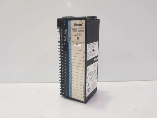
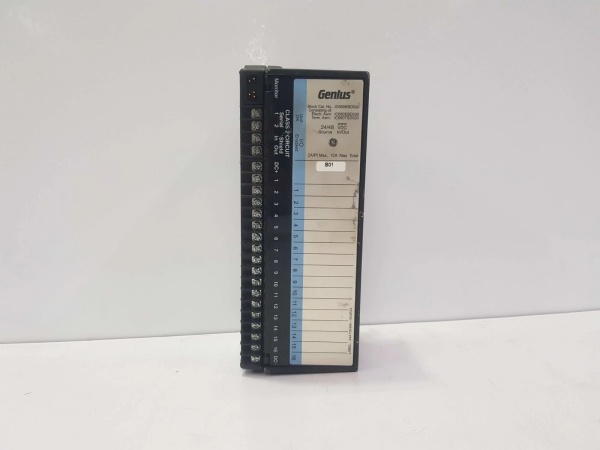
- Terminals: 30 screw terminals (24 I/O + 6 power/ground)

GE IC660BBD020
The Real-World Problem It Solves
Nuclear power plants operate with zero tolerance for communication failures between sensor networks and main safety systems. The IC660EBD024 provides redundant communication paths that prevent data loss if a bus segment becomes damaged.
Where you’ll typically find it:
- Chemical plant emergency shutdown (ESD) systems
- Power generation turbine vibration monitoring arrays
- Pharmaceutical cleanroom environmental control systems
This module eliminates single-point bus failure points that could lead to catastrophic safety incidents.
Hardware Architecture & Under-the-Hood Logic
The IC660EBD024 includes dual bus interface microprocessors that provide redundant communication paths to the main PLC. This allows the module to maintain data transmission even if one bus path fails due to wiring damage or power loss.
- Field signals pass through screw terminals to input buffer circuits
- Optical isolators convert analog signals to digital pulses for transmission
- Dual microprocessors handle signal processing and health monitoring
- Data packets are transmitted across both bus interfaces simultaneously
- Main PLC compares data from both channels to verify integrity
- Diagnostic LEDs indicate channel status, bus health, and power presence
Field Service Pitfalls: What Rookies Get Wrong
Mixing Input/Output Wire GaugesTechnicians often use #22 AWG wire for all connections, which works for inputs but causes voltage drop on outputs carrying full 2A load. This leads to actuator under-voltage faults that are hard to trace in large cabinets.
- Field Rule: Use #18 AWG minimum for output wiring runs over 20ft to maintain voltage integrity.
Ignoring Bus TerminationNew engineers forget to add terminators on redundant bus segments running the IC660EBD024. This causes signal reflections that create intermittent data corruption appearing as random sensor errors.
- Quick Fix: Verify bus terminators are installed at both endpoints of redundant communication paths.
Loose Power ConnectorI’ve seen a module fail after 6 months of operation at a chemical plant because the power connector wasn’t fully seated in the backplane. Vibration from adjacent pumps worked the connector loose over time, causing intermittent power loss.
- Field Rule: Always pull on the cable boot, not the wires, to ensure proper seating and check connector locks before closing cabinet doors.
Please note: The listed price is for reference only and is not binding. Final pricing and terms are subject to negotiation based on current market conditions and availability.


