
Description
Hard-Numbers: Technical Specifications
- Protocol Support: Genius Bus (153.6K baud standard)
- Port Count: 8 configurable circuits (4 isolated groups of 2)
- Input/Output Voltage: 115VAC nominal (93-132VAC range) or 125VDC nominal (105-132VDC range)
- Output Type: Sourcing
- Output Load Current: 2A steady-state per circuit
- Maximum Inrush Current: 25A (2 cycles AC, 10ms peak DC)
- Maximum Block Output Current: 15A @ 35°C, 7.5A @ 60°C
- Input Response Time: AC: 2ms + filter; DC: 0.8ms + filter
- Selectable Input Filter Times: 10-100ms in 10ms increments
- Output Response Time: Zero crossing (AC), <1ms (DC)
- Output Switching Frequency: Once per second at maximum inrush (0.5Hz rated)
- Output Leakage Current: 7mA AC (off state), 2mA DC (off state)
- Output Voltage at Open Circuit: 65V AC, 40V DC
- Minimum Load Requirements: Resistive 25mA AC/10mA DC; Inductive 40mA AC/10mA DC (with no-load disabled)
- No-Load Enabled Threshold: Inductive 50mA AC/50mA DC
- Electronic Fusing: Internal short circuit trip – 100ms (AC), 10ms (DC) long time trip
- Output Diagnostics: Short Circuit, Overload, No Load, Overtemperature, Loss of I/O Power, Failed Switch
- Heat Dissipation: 16.8W max (8 inputs), 45.6W max (8 outputs at 2A)
- Required Control Power: 8W maximum (block only)
- Power Supply Dropout Time: 1 cycle (16.7ms @ 60Hz, 20ms @ 50Hz, 10ms @ DC)
- Operating Temperature: 0°C to +60°C (+32°F to +140°F)
- Storage Temperature: -40°C to +100°C (-40°F to +212°F)
- Humidity: 5% to 95% non-condensing
- Dimensions: 8.83″ x 3.50″ x 3.94″ (22.44cm x 8.89cm x 10.00cm)
- Weight: 4 lbs (1.8 kg)
- Required HMM: IC660HHM501 only
- CPU Redundancy: Supported
- Output Pulse Test: Configurable

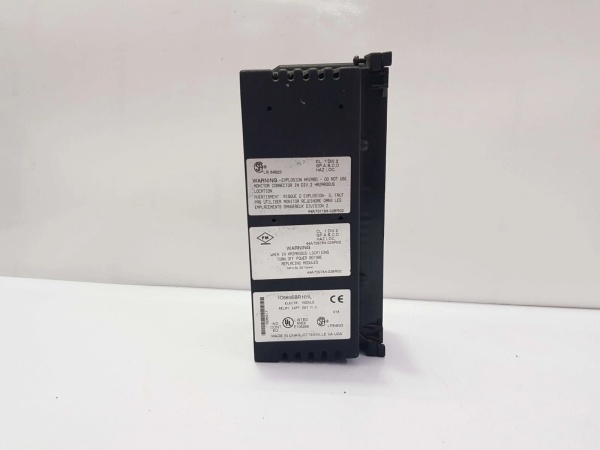
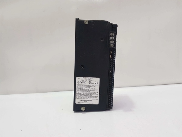
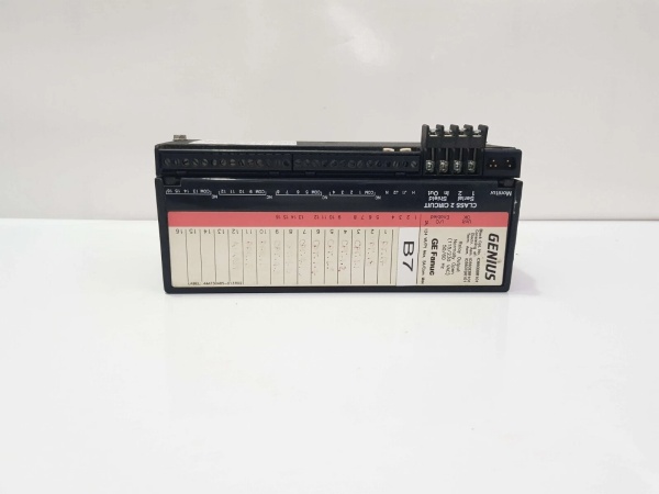
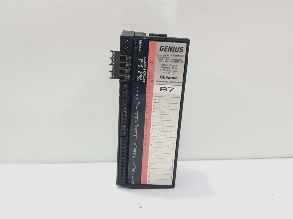
GE IC660BBR101
The Real-World Problem It Solves
This block eliminates the need for separate AC and DC input/output modules by supporting both 115VAC and 125VDC on the same configurable circuits. Group isolation (250VAC/VDC) lets you mix different voltage levels safely. Failed switch diagnostics compare commanded output state to actual internal switch state, catching stuck or failed outputs before they cause problems.
Where you’ll typically find it:
- Chemical Processing Plants: Interfacing 115VAC limit switches and 125VDC solenoid valves on batch process skids
- Power Generation Systems: Controlling 125VDC indicating lights and monitoring 115VAC auxiliary relay contacts in turbine controls
- Water Treatment Facilities: Operating 115VAC motor starters and monitoring 125VDC level sensors in dosing systems
Bottom-line value: Supports mixed AC/DC voltages on one block with configurable input/output, provides group isolation for safety-critical applications, and failed switch diagnostics detect output faults before they impact the process.
Hardware Architecture & Under-the-Hood Logic
This is an isolated I/O block where each of the 8 circuits can function as input or output independently, arranged in four isolated groups of two channels each. Each group provides 250VAC/VDC isolation from other groups and ground, enabling mixed voltage applications. The block supports both 115VAC and 125VDC operation on a per-circuit basis. Electronic fusing protects outputs with 100ms trip time for AC and 10ms for DC. Failed switch diagnostics compare commanded output state to actual internal switch state to detect failed switching elements.
Internal Signal Flow:
- Power applied to terminals 5 and 6 provides block control power (8W max) and I/O power for circuits
- For AC circuits: Field power connects to H (phase) and N (neutral) terminals per group
- For DC circuits: Field power connects to H (positive) and N (negative) terminals per group
- Input circuits (AC): Voltage divided through capacitor network (22μF for BBS102), filtered (10-100ms), rectified, and opto-isolated to logic
- Input circuits (DC): Voltage divided through resistor network (13KΩ to N), filtered (10-100ms), and opto-isolated to logic
- Tristate inputs require 5.1KΩ resistor across dry contacts of input device
- Output circuits: CPU commands trigger output drivers, providing power to load via internal switching devices
- AC outputs use zero-crossing switching for reduced EMI; DC outputs use fast switching (<1ms)
- Current sensing monitors output current, triggering electronic fuse at overload (100ms AC, 10ms DC)
- Failed switch diagnostics compare commanded output state to actual switch state, reporting mismatches
- Diagnostics continuously monitor for overtemperature, I/O power loss on circuit pairs, no-load, short circuit, and failed switch
- Processed I/O data and diagnostic status transmitted over Genius bus to controller
GE IC660BBR101
Field Service Pitfalls: What Rookies Get Wrong
Misunderstanding Group Isolation Limits
The block provides 250VAC/VDC isolation between groups, but techs assume this means complete circuit isolation and mix voltage levels within groups incorrectly. Connecting 115VAC and 125VDC circuits to the same group violates isolation boundaries. I’ve seen damaged output groups because someone mixed AC and DC circuits in the same isolated group.
- Field Rule: Treat each group of 2 circuits as an isolated island. Keep voltage types consistent within each group—if using 115VAC circuits in one group, do not add 125VDC circuits to the same group. Use different groups for different voltage levels. Verify isolation requirements before mixing voltages on the same block.
Incorrect Tristate Input Resistor Values
Tristate inputs require a 5.1KΩ resistor across dry contacts, but techs skip this component or use wrong values. Without the resistor, tristate diagnostics don’t work properly and input states become erratic. I’ve seen false “open wire” alarms because someone omitted the required 5.1KΩ resistor.
- Field Rule: Always install 5.1KΩ resistor across dry contacts when using tristate input configuration. Verify resistor tolerance (1% recommended) and power rating (1W minimum) matches requirements. Never use tristate inputs without the resistor—this is not optional hardware, it’s required for proper operation.
Disabling No-Load Detection for Wrong Reasons
The block detects no-load conditions and reports them, but techs disable this feature when using low-current devices like indicator LEDs. This masks actual load failures and defeats diagnostic capability. I’ve found burned-out indicator lights that had been dark for weeks because no-load detection was disabled to 终止 nuisance alarms.
- Field Rule: Keep no-load detection enabled on all output circuits. For low-current devices below minimum thresholds, add parallel load resistors to meet minimum requirements (25mA AC resistive, 10mA DC resistive). An open circuit on a critical output should always generate an alarm.
Overlooking AC vs DC Circuit Configuration
The block supports both 115VAC and 125VDC on a per-circuit basis, but techs wire all circuits assuming AC configuration and apply DC power incorrectly. This damages input conditioning networks or output switching devices. I’ve seen destroyed DC input circuits because someone applied 115VAC to a circuit configured for 125VDC.
- Field Rule: Verify AC/DC configuration for each circuit before applying power. Check HHM configuration to ensure circuit type matches actual field wiring. AC circuits require H/N connections with proper grounding; DC circuits require H (positive) and N (negative) connections. Never apply AC to a DC-configured circuit or vice versa.
Forgetting Failed Switch Diagnostics Purpose
The block performs failed switch diagnostics by comparing commanded output state to actual internal switch state, but techs ignore these diagnostics or assume the block is faulty when they trigger. This diagnostic is telling you the internal switching element failed—this is real information, not a nuisance alarm. I’ve seen techs replace perfectly good blocks because they didn’t understand failed switch diagnostics indicate a real hardware problem.
- Field Rule: Treat failed switch diagnostics as serious hardware fault indicators. When failed switch diagnostic triggers, the internal switching element for that output has failed and requires block replacement or repair. Do not clear the alarm and continue operation—the output cannot be trusted. Log all failed switch events to identify patterns.
Overloading Block Current Capacity
Each channel handles 2A, but the total block current is limited (15A @ 35°C, 7.5A @ 60°C). Techs load all 8 circuits at 2A (16A total), causing thermal shutdown or electronic fuse trips. I’ve seen blocks in overtemperature lockout because someone didn’t calculate total current rating and derated for ambient temperature.
- Field Rule: Calculate total block current and derate at high temperatures. At 60°C ambient, maximum block current drops to 7.5A—only 3-4 circuits at 2A. Spread loads across multiple blocks if needed. Verify ambient temperature and calculate derated current before commissioning high-current applications.
Commercial Availability & Pricing Note
Please note: The listed price is for reference only and is not binding. Final pricing and terms are subject to negotiation based on current market conditions and availability.


