
Description
Hard-Numbers: Technical Specifications
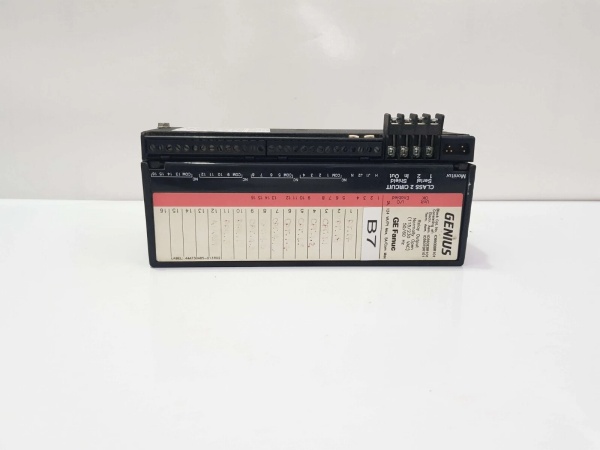
- Protocol Support: Genius Bus (153.6K baud)
- Port Count: 16 output circuits (4 groups of 4)
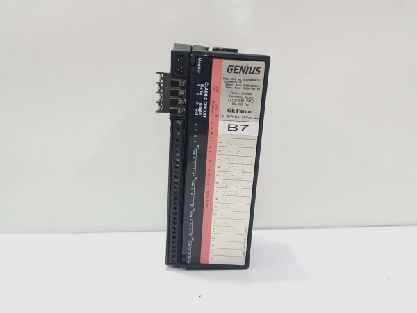
- Output Type: Normally Open (NO) Relay
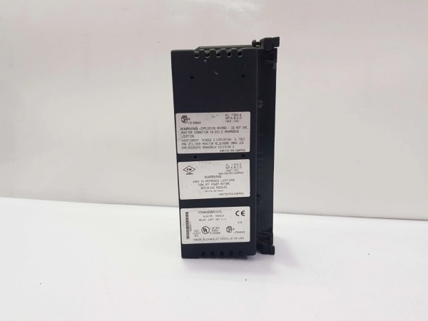
- Relay Type: Fixed coil moving armature
- Rated Block Voltage: 115VAC or 230VAC (jumper selectable)
- Operating Voltage Range: 93-132VAC (115VAC setting) or 185-265VAC (230VAC setting)
- Output Voltage Range: 5V to 250VAC or 5V to 220VDC
- Maximum Output Current: 2A per circuit
- Maximum Switching Power: 60 Watts or 125VA per circuit
- Maximum Inrush Current: 2A per circuit
- Maximum Switching Frequency: 20 cycles/minute (inductive loads)
- Output Turn-On Delay: 5ms maximum
- Output OFF Leakage Current: 0.1mA
- Minimum Recommended Load: 10mA
- Power Requirement: 87mA at 115VAC
- Power Supply Dropout Time: 1 cycle (16.7ms @ 60Hz, 20ms @ 50Hz)
- Isolation Rating: 1500VAC (all outputs to chassis ground, between output groups)
- Heat Dissipation: 10.1W maximum (16 outputs on)
- Operating Temperature: 0°C to +60°C (+32°F to +140°F)
- Storage Temperature: -40°C to +100°C (-40°F to +212°F)
- Dimensions: 8.83″ x 3.34″ x 3.91″ (22.44cm x 8.48cm x 9.93cm)
- Weight: 4 lbs (1.8 kg)
- Required HMM: IC660HHM501 only
- CPU Redundancy: Supported
- Bus Switching Module (BSM): Configurable as BSM controller

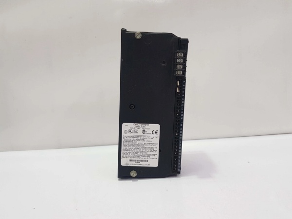
GE IC660BBR101
The Real-World Problem It Solves
This block eliminates the need for solid-state drivers by using mechanical relays that handle both AC and DC loads on the same module. Selectable 115/230VAC block power via jumpers adapts to different plant voltages without hardware changes, and CPU redundancy support ensures continuity in high-availability systems. Individual group isolation lets you mix different voltage levels on the same block.
Where you’ll typically find it:
- Machine Control Panels: Driving indicator lamps, small contactor coils, and alarm horns on assembly lines
- Process Control Skids: Operating 24VDC solenoid valves and 115VAC indicating lights in chemical processing
- Water Treatment Facilities: Controlling pump starter coils and status lights from distributed Genius I/O nodes
Bottom-line value: Provides flexible AC/DC switching without external drivers, supports mixed load voltages on the same module, and delivers CPU redundancy for high-availability distributed control systems.
Hardware Architecture & Under-the-Hood Logic
This is a standalone relay output block that communicates via Genius bus without requiring a baseplate or rack. It uses fixed-coil moving armature relays for mechanical switching of loads, with four isolated groups of four outputs each. Block power (115VAC or 230VAC) is selected via jumpers on the Terminal Assembly and powers the relay coils. The block supports CPU redundancy configurations and can function as a Bus Switching Module (BSM) for bus control applications.
Internal Signal Flow:
- Block power (115VAC or 230VAC) applied to power terminals, jumper selects operating voltage range
- Genius bus communication received via terminals 1-4, parsed by microprocessor
- CPU output commands processed by local microprocessor, determining which relay coils to energize
- Relay coil drivers receive logic signals, energize appropriate relay coils
- Fixed-coil moving armature mechanism closes when coil energized, opening contacts when de-energized (normally open configuration)
- Load power applied to relay contacts (5-250VAC/5-220VDC from external source)
- Relay contacts close or open based on coil state, switching power to connected loads
- Current limited to 2A per circuit by relay contact rating and external fusing
- Individual circuit LEDs reflect relay coil state (not load status)
- Unit OK and I/O Enabled LEDs display block health and communication status
- In redundancy mode, block monitors primary and secondary CPU signals for failover
- In BSM mode, block controls Genius bus switching functions instead of standard I/O operations
GE IC660BBR101
Field Service Pitfalls: What Rookies Get Wrong
Ignoring Switching Frequency Limits
The relay outputs are rated for maximum 20 cycles/minute on inductive loads, but techs drive them at PLC scan rates (50-100ms intervals) for high-speed applications. This destroys relay contacts in weeks. I’ve seen blocks with welded contacts because someone ran a 2Hz timing sequence through a relay output meant for intermittent switching.
- Field Rule: Calculate actual switching frequency based on application requirements. For high-speed switching (>1Hz), use solid-state output blocks (IC660BBD021/IC660BBD025). Reserve IC660BBR101 for applications requiring intermittent operation (pilot lights, alarm horns, occasional valve actuation). Never exceed 20 cycles/minute on inductive loads.
Missing External Fusing on Relay Outputs
The block has no internal fuses on output circuits, but techs wire loads directly without external protection. When a load shorts, the 2A relay contact welds from overload current. I’ve found blocks with destroyed relays because someone connected a 5A motor starter coil directly without fusing.
- Field Rule: Install external fuses (2A or less) in series with each output circuit to protect relay contacts from overload. Size fuses based on actual load current, not relay rating. Use fast-acting fuses for better protection. Never rely on the relay contact rating alone—short circuits draw far more than 2A.
Wrong Block Power Jumper Setting
The block supports 115VAC or 230VAC block power via jumpers, but techs fail to verify jumper settings match actual plant voltage. Applying 230VAC to a block set for 115VAC destroys power supply components instantly. I’ve seen blocks blown because someone swapped a 115VAC block into a 230VAC panel without checking jumpers.
- Field Rule: Verify jumper settings match actual supply voltage before applying power. Check jumpers on the Terminal Assembly during installation. If converting from 115VAC to 230VAC operation or vice versa, reconfigure jumpers and verify with multimeter before energizing. Label the block with its configured voltage to prevent errors.
Exceeding Group Isolation Limits
The four output groups provide 1500VAC isolation between groups, but techs mix voltage levels within groups incorrectly. Connecting 24VDC and 230VAC loads to the same group creates potential isolation issues. I’ve seen damaged output groups because someone wired a 24VDC solenoid and a 230VAC light to the same group of four.
- Field Rule: Keep load voltage types consistent within each group of four outputs. If mixing 24VDC and 230VAC loads, assign them to different groups to maintain isolation integrity. Verify ground references don’t create isolation violations. When in doubt, use separate blocks for different voltage levels.
Misinterpreting LED Indications
Individual output LEDs reflect relay coil state, not load status, but techs assume the LED OFF means no power to load. If the load side power fails, the LED stays ON even though no output exists. I’ve seen techs troubleshooting nonexistent problems because they trusted the LED instead of measuring voltage at the load.
- Field Rule: LEDs indicate coil energization only, not load power delivery. Verify actual output voltage at the load terminals with a multimeter. LED ON = coil energized (contact closed), LED OFF = coil de-energized (contact open). If LED is ON but load doesn’t operate, check load power supply, wiring, and the load itself—not the block.
Overtorquing Terminal Screws
Recommended torque is 6 in/lb, but techs crank terminals down with screwdrivers to “make sure they’re tight.” This strips terminal screws or damages connector blocks. I’ve found terminals that won’t release wire because the screw is cross-threaded from overtightening.
- Field Rule: Use a torque screwdriver set to 6 in/lb (0.678 N/M) for all terminal connections. Do not overtighten—proper torque ensures good contact without damage. If terminals feel loose after proper torque, check wire gauge and terminal compatibility before applying more force.
Commercial Availability & Pricing Note
Please note: The listed price is for reference only and is not binding. Final pricing and terms are subject to negotiation based on current market conditions and availability.


