
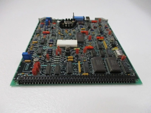
Description
Hard-Numbers: Technical Specifications
- Input Points: 16 discrete AC inputs
- Nominal Input Voltage: 115VAC
- Input Voltage Range: 93-132VAC
- Frequency Range: 47-63Hz
- Input Impedance: 11.6kΩ (typical)
- Input Thresholds: Programmable 25-85% for ON/OFF states
- Short Wire Threshold: Fixed 10-90% for short circuit detection
- Selectable Input Filter: 10-100ms in 10ms increments
- Processing Time: 1ms (plus filter delay)
- Heat Dissipation: 28W maximum with all 16 inputs ON
- Block Current: 80mA maximum from bus power
- Input Circuit Current: 200mA per input circuit maximum
- Isolation: 1500V from input to ground/serial bus
- Diagnostics: Open wire, short circuit detection on each input
- Operating Temperature: 0°C to +60°C (32°F to +140°F)
- Storage Temperature: -40°C to +100°C (-40°F to +212°F)
- Humidity Range: 5% to 95% non-condensing
- Weight: 4 lbs (1.8 kg)
- Dimensions: 8.8 x 3.3 x 3.9 inches

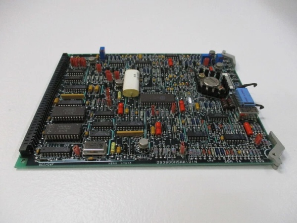
DS3800HSAA1U1N
The Real-World Problem It Solves
The IC660BBD110 solves the challenge of distributed AC sensor monitoring in large-scale industrial environments. Traditional PLC I/O requires remote racks or baseplates near field devices, increasing wiring complexity and installation costs. This Genius I/O block communicates directly over the serial bus protocol, eliminating the need for a central rack while retaining local intelligence. Programmable input thresholds adapt to varying sensor voltages and signal conditions, while advanced wire fault diagnostics reduce downtime by identifying open wiring or short circuits before they cause system failures.
Where you’ll typically find it:
- Manufacturing Automation: Monitoring safety interlocks, emergency 终止 buttons, and position sensors in large assembly lines and conveyor systems.
- Pulp and Paper: Detecting limit switches and position sensors on paper machines and processing equipment across extended plant floors.
- Petrochemical Plants: Monitoring valve position indicators and pressure switches in hazardous area control systems requiring high isolation ratings.
- Water Treatment: Monitoring flow switches and pump status indicators across sprawling water treatment facilities with distributed control requirements.
Bottom-line value: Reduces installation time by 50% compared to traditional remote I/O racks through distributed wiring architecture, while diagnostic features reduce mean time to repair (MTTR) by up to 70% through proactive wire fault detection.
Hardware Architecture & Under-the-Hood Logic
The IC660BBD110 consists of two primary components: an Electronics Assembly and a Terminal Assembly. The Electronics Assembly contains the input circuitry, signal conditioning, and Genius bus communication hardware, while the Terminal Assembly provides screw-type field wiring terminals and diagnostic LEDs. Each input circuit includes an isolation barrier, signal conditioning, and threshold comparison circuitry that compares input voltage against programmable ON/OFF levels. The module draws control power directly from the input voltage source, eliminating the need for an external power supply.
Internal Signal Flow:
- Field Input: 115VAC sensor signal enters via screw terminals on the Terminal Assembly.
- Signal Conditioning: Input voltage is conditioned and passed through an isolation barrier to protect electronics and communication circuits.
- Threshold Comparison: Signal voltage is compared against programmable ON/OFF thresholds (25-85% of input voltage).
- Filter Processing: Selectable digital filtering (10-100ms) reduces electrical noise and contact bounce.
- Diagnostic Logic: Continuously monitors for open wiring (above threshold with no current) and short circuits (below threshold with abnormal current).
- Status Output: Individual circuit LEDs reflect input state (ON/OFF/fault), with unit OK and I/O enable LEDs indicating block status and bus communication.
- Genius Bus Communication: Processed input data is transmitted to the PLC over the serial bus, with configuration data stored in the Terminal Assembly for quick electronics replacement.
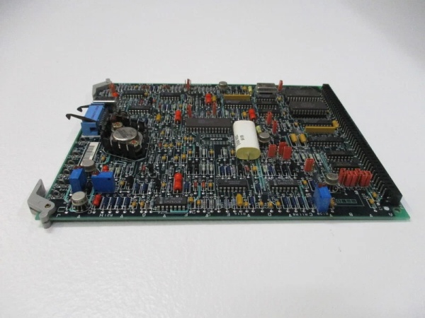
DS3800HSAA1U1N
Field Service Pitfalls: What Rookies Get Wrong
Incorrect Input Threshold Configuration
The IC660BBD110’s programmable ON/OFF thresholds allow customization for different sensor types, but technicians frequently leave them at default settings (50% for both states) regardless of the actual sensor characteristics. This causes false triggering with low-voltage sensors or missed signals with high-threshold requirements. I’ve seen entire production lines go into emergency 终止 mode because the threshold was set too low, detecting sensor contact bounce as actual signals.
- Field Rule: Always set thresholds based on the specific sensor’s voltage characteristics. For pushbuttons and simple switches, use 25% ON and 75% OFF thresholds for reliable noise rejection. For proximity sensors and other voltage-dependent devices, match thresholds to the manufacturer’s voltage output specifications to avoid false triggers or missed signals.
Neglecting Wire Fault Diagnostics
The block’s open wire and short circuit diagnostic features are often disabled to reduce false alarms, but this prevents detection of critical wiring failures. Technicians sometimes disable diagnostics entirely rather than adjusting thresholds to eliminate nuisance alarms, leading to undetected wiring faults that cause unexpected system shutdowns or safety hazards. I’ve seen a water treatment plant shut down due to a failed float sensor that went undetected because wire fault diagnostics were disabled.
- Quick Fix: Keep wire fault diagnostics enabled at all times, adjusting threshold levels as needed to eliminate nuisance alarms rather than disabling the feature entirely. Monitor diagnostic events closely during commissioning to set appropriate thresholds that differentiate between genuine wire faults and normal sensor operation.
Improper Grounding Practices
The IC660BBD110’s 1500V isolation rating protects internal electronics, but technicians frequently ground sensor shields or common terminals incorrectly, creating ground loops that introduce noise and interfere with communication. Improper grounding can also reduce the isolation effectiveness, making the block vulnerable to electrical transients from other equipment.
- Field Rule: Follow the grounding recommendations in the Genius I/O User’s Manual strictly. Connect sensor shields only at one end (preferably at the sensor) to prevent ground loops. Use dedicated ground wires for the block’s ground terminal, not sharing it with other equipment grounds that may carry noise or transient currents.
Ignoring Filter Time Settings
The selectable input filtering feature (10-100ms) reduces contact bounce and electrical noise, but technicians often use the shortest filter time (10ms) regardless of application requirements. This can lead to false detections in noisy environments, especially with mechanical switches that exhibit contact bounce longer than 10ms. Conversely, overly long filtering times can prevent detection of fast-switching signals or create unacceptable system latency.
- Field Rule: Set filter time based on the specific application requirements and sensor characteristics. Use 10-20ms for high-speed applications with low-noise electrical environments, 50-100ms for mechanical switches with significant contact bounce, and 30-50ms for general-purpose applications. Test filtering times during commissioning to balance noise rejection and response time.
Incorrect Module Installation Orientation
The IC660BBD110 can be installed right-side-up or upside down, but technicians frequently install it in upside-down orientation without considering the location of the bus terminals and diagnostic LEDs. This makes wiring bus connections more difficult and hides status indicators behind equipment or in hard-to-see locations.
- Field Rule: Install the block right-side-up in most applications to facilitate bus connection wiring and easy access to status LEDs. If space constraints require upside-down installation, ensure bus connection terminals are easily accessible and LEDs remain visible for status monitoring and troubleshooting. Document installation orientation for future maintenance.
Overlooking Heat Dissipation Limits
The block dissipates up to 28W when all 16 inputs are ON, but technicians often install multiple blocks in enclosed cabinets without proper ventilation. This can cause temperature buildup that exceeds the 60°C maximum operating temperature, leading to performance degradation or component failure. I’ve seen entire Genius I/O systems fail in sealed cabinets where heat buildup caused intermittent communication errors and input drift.
- Field Rule: Calculate total heat dissipation when designing enclosures, especially with multiple blocks operating at full capacity. Ensure adequate ventilation or forced cooling in enclosed cabinets to keep temperatures below 60°C. Install temperature monitoring devices in critical applications to detect overheating conditions before they cause system failures.
Commercial Availability & Pricing Note
Please note: The listed price is for reference only and is not binding. Final pricing and terms are subject to negotiation based on current market conditions and availability. This product may be discontinued by the manufacturer, so pricing may vary significantly based on remaining inventory, refurbishment quality, and source of supply.


