
Description
Hard-Numbers: Technical Specifications
- I/O Channels: 8 configurable discrete circuits (each: input/output)
- Input/Output Voltage: 115VAC nominal
- Input Voltage Range: 93-132VAC
- Output Load Current: 2A steady-state RMS per channel
- Maximum Inrush Current: 25A peak (up to 2 cycles), 14A peak (2-6 cycles)
- Maximum Block Output Current: 15A @ 35°C, 7.5A @ 60°C
- Input Response Time: 2ms + filter time
- Output Response Time: Zero-crossing switching
- Input Filter Time: 10-100ms (selectable in 10ms increments)
- Power Supply: 93-132VAC (tapped from I/O device voltages)
- Frequency: 47-63Hz
- Power Supply Dropout Time: 1 cycle (16.7ms @ 60Hz, 20ms @ 50Hz)
- Heat Dissipation: 16W maximum (8 inputs), 43.5W maximum (8 outputs at 2A)
- Standby Power: 8.5W (all I/O off)
- Isolation: 1500V block-to-block
- Electronic Fusing: Trips at 30A (output on) or 20A after 2 cycles, 5ms response
- Output Leakage: <7mA @ 115VAC
- Output Voltage at Open Circuit: 65V (OUT to N)
- Minimum Off-State Voltage: 60V RMS
- Maximum Off-State Current: 1.5mA (non-tristate), 6mA RMS (tristate)
- Output Voltage Drop: 2.5V @ 2A, 10V @ 30A inrush
- Maximum Switching Frequency: 0.5Hz + 1ms
- Recommended Minimum Load: 25mA resistive, 40mA inductive (with no-load disabled), 50mA (with no-load enabled)
- Diagnostics: Short circuit, overload, no-load detection, failed switch, overtemperature, open wire (tristate)
- Status LEDs: Unit OK, I/O Enabled, individual LED per circuit
- Operating Temperature: 0°C to +60°C
- Storage Temperature: -40°C to +100°C
- Dimensions: 8.83″ x 3.34″ x 3.91″ (22.44cm x 8.48cm x 9.93cm)
- Weight: 4 lbs (1.8 kg)
- Hand-Held Monitor Compatibility: IC66*HHM501 required

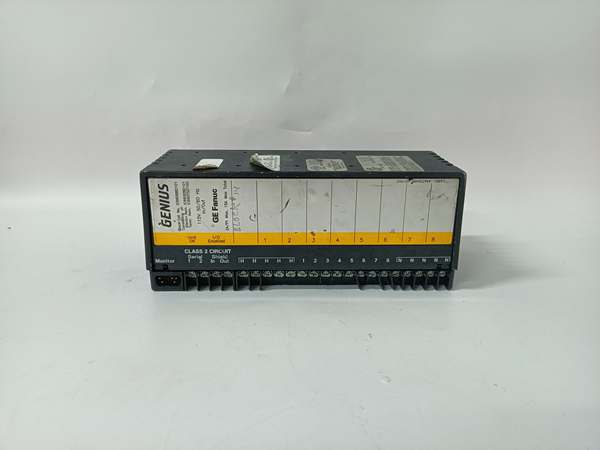
GE IC660BBD101
The Real-World Problem It Solves
This block provides 115VAC I/O with electronic short circuit protection that trips in 5ms, preventing damage during fault conditions. Each circuit independently configures as input or output, so you don’t need separate modules for mixed installations. Low leakage current (<7mA) makes it suitable for applications where leakage current matters for safety compliance.
Where you’ll typically find it:
- Chemical processing plants interfacing with 115VAC limit switches and pilot lights
- Power generation facilities controlling 115VAC solenoid valves and indicating lights
- Pulp and paper mills with 115VAC discrete sensor and actuator requirements
Bottom-line value: Eliminates need for separate input/output modules by mixing configurations on one block, electronic fusing provides fast fault protection, and low leakage characteristics support safety-critical applications requiring minimal off-state current.
Hardware Architecture & Under-the-Hood Logic
This is a low-leakage AC discrete I/O block where each circuit can function as input or output independently. The block taps control power directly from the 115VAC field device voltages wired to terminals, so no separate block power supply is required. All 8 circuits share a common but provide electronic short circuit protection with 5ms trip time. Input circuits feature voltage sensing with configurable filtering, while outputs use zero-crossing switching to reduce electrical noise and inrush currents.
Internal Signal Flow:
- Field device 115VAC connected to terminals provides both control power and I/O voltage
- Input circuits: Voltage sensed through voltage divider, filtered (10-100ms in 10ms increments), digitalized via opto-isolator at 2ms + filter time
- Output circuits: Processor drives output triac at zero-crossing, provides up to 2A steady-state current to load, electronic fuse monitors for overcurrent conditions
- Electronic fusing: Continuously monitors output current, trips circuit within 5ms if current exceeds 30A (on-state) or 20A after 2 cycles
- Diagnostics monitor each circuit for short circuit, overload, no-load, failed switch, overtemperature, and open wire (tristate inputs)
- Processed I/O data and diagnostic status transmitted over Genius bus to controller
- Individual circuit LEDs provide per-point status indication (input ON/OFF, output ON/fault)
GE IC660BBD101
Field Service Pitfalls: What Rookies Get Wrong
Exceeding Block Output Current Limits
The block maximum output current is 15A @ 35°C and 7.5A @ 60°C, but techs treat this as per-channel rating. Running all 8 outputs at 2A in a hot cabinet (50°C+) exceeds the 7.5A limit, causing thermal shutdown. I’ve found blocks in thermal cutout with 6 outputs active because nobody calculated cumulative current at actual ambient temperature.
- Field Rule: Calculate total output current based on actual ambient temperature, not maximum ratings. At 60°C ambient, you can only run 3-4 outputs at 2A simultaneously. For high-density output applications, derate channels or install forced cooling. Never assume 8 channels at 2A is possible in real-world conditions.
Disabling No-Load Detection for Wrong Reasons
The block detects no-load condition (<50mA) and reports it, but techs disable this feature when using high-impedance pilot lights or indicator towers that draw below threshold. This masks legitimate load failures and defeats diagnostic capability. I’ve found burned-out indicator lamps that had been dark for weeks because no-load detection was disabled.
- Field Rule: Use high-quality indicators that meet minimum load requirements (50mA). If you must use low-current devices, install parallel load resistors to meet threshold. Keep no-load detection enabled on all output circuits. An open circuit on a critical output should always generate an alarm.
Wrong Filter Time on Safety Inputs
Techs set input filters to 100ms on everything to eliminate noise, including safety-critical E-终止 circuits and limit switches. This adds unacceptable delay to safety inputs, causing hazards. I’ve seen E-终止 circuits take 100+ms to trigger because someone configured 100ms filter on safety inputs.
- Field Rule: Never exceed 10-20ms filter on safety-critical inputs (E-stops, emergency shutdowns, safety interlocks). Use 10-20ms for general-purpose inputs (pushbuttons, selector switches). Reserve 80-100ms only for extremely noisy environments on non-critical inputs. Safety response time always trumps noise reduction.
Overlooking Output Voltage at Open Circuit
The block outputs 65V at open circuit when off, but techs assume it’s zero and work on live circuits. This creates shock hazard when troubleshooting or replacing loads. I’ve seen technicians get shocked expecting dead circuits because they didn’t understand off-state voltage.
- Field Rule: Treat all outputs as live even when off. Verify zero voltage with a multimeter before touching terminals. The 65V off-state voltage comes from the triac leakage characteristic and is normal for this block. Never rely on output status LEDs alone for safety verification.
Mixing AC Phases on Single Common
All 8 circuits share a common, but techs connect inputs/outputs from different AC phases to the same block. This creates phase-to-phase shorts through the common, destroying circuits. I’ve seen blocks destroyed because someone connected Phase A inputs and Phase B outputs to the same block.
- Field Rule: Connect all I/O circuits to the same AC phase when possible. If you must use different phases, use separate blocks or verify isolation rating (1500V) exceeds phase-to-phase voltage difference. Never mix phases on the same block without verifying phase difference is within isolation limits.
Ignoring Electronic Fuse Reset Requirements
Electronic fuses trip at 30A/20A and require CPU or handheld monitor command to reset, but techs assume they auto-reset. They cycle power, find circuits still tripped, and replace good blocks. I’ve seen perfectly good blocks scrapped because someone cycled power instead of issuing the reset command.
- Field Rule: When an output circuit trips due to overcurrent, use handheld monitor or CPU command to reset the electronic fuse. Power cycling does not reset electronic fuses. Verify the fault condition is cleared before resetting. Log all fuse trips to identify recurring overload issues.
Incorrect Terminal Assembly Compatibility
The block requires specific Terminal Assembly versions, but techs install incompatible assemblies when replacing hardware. This causes incorrect operation or prevents the block from working. I’ve seen functional Electronics Assemblies labeled “faulty” because someone installed the wrong Terminal Assembly.
- Field Rule: Verify Terminal Assembly version matches block requirements before installation. Check the compatibility matrix in the manual. Never mix assemblies between different block types. If replacing a block, replace the complete assembly or verify compatibility of individual components.
Commercial Availability & Pricing Note
Please note: The listed price is for reference only and is not binding. Final pricing and terms are subject to negotiation based on current market conditions and availability.


