
Description
Hard-Numbers: Technical Specifications
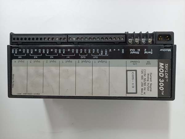
- Input Channels: 4 isolated 4-20mA inputs
- Output Channels: 2 isolated 4-20mA outputs
- Input Range: 4-20mA (overrange 0-25mA)
- Output Range: 4-20mA (overrange 0-24mA)
- Input Accuracy: ±0.1% full scale (at 25°C)
- Output Accuracy: ±0.15% full scale (at 25°C)
- Input Resolution: 1µA
- Output Resolution: 6µA
- Input Conversion Time: 16.6ms to 400ms (user-selectable)
- Output Update Time: 6-8ms typical
- Input Excitation: 24VDC open circuit, <75mA short circuit current
- Input Loop Impedance: 1000Ω maximum (0-20mA), 800Ω maximum (20-25mA)
- Output Load: 0-850Ω
- Power Supply: 115VAC / 125VDC nominal
- Operating Voltage Range: 93-132VAC / 105-145VDC
- Power Consumption: 250mA (AC) / 140mA (DC) maximum
- Heat Dissipation: 12W maximum
- Isolation: 1500V block-to-block, 1500V group-to-group, 1500V channel-to-channel
- Status LEDs: Unit OK, I/O Enabled
- Operating Temperature: 0°C to +60°C
- Storage Temperature: -40°C to +100°C
- Dimensions: 8.83″ x 3.34″ x 3.91″ (22.44cm x 8.48cm x 9.93cm)
- Weight: 4 lbs (1.8 kg)
- Hand-Held Monitor Required: Version 3.7 or later
- BSM Control: Dedicated output to control IC66*BSM021 Bus Switching Module

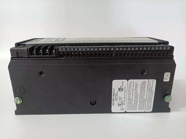
IC660BBA104
The Real-World Problem It Solves
This block eliminates external 24VDC power supplies for 4-20mA loops by providing loop power directly from each input channel. You get 1500V isolation on every channel, so ground loops and common mode noise won’t corrupt your process signals. The outputs drive current loops up to 850Ω without external power, cutting wiring and hardware costs.
Where you’ll typically find it:
- Chemical process plants interfacing with 4-20mA pressure and flow transmitters
- Power generation stations controlling governor valves and turbine actuators
- Water treatment facilities with remote transmitter clusters requiring distributed I/O
Bottom-line value: Removes need for field power supplies and isolators in most 4-20mA applications, reducing cabinet space and installation cost by 40-60% while providing channel-level isolation that prevents ground loop problems in noisy environments.
Hardware Architecture & Under-the-Hood Logic
This is a true current-source block—each input channel includes its own 24VDC excitation supply and voltage-to-frequency converter with opto-isolation. Inputs are fully isolated from each other and from the outputs. The two outputs share a common circuit but are isolated from inputs and use dual 12-bit DACs with feedback for accuracy. A dedicated digital output drives the Bus Switching Module for redundancy.
Internal Signal Flow:
- 4-20mA current from field transmitter enters input, 24VDC loop power supplied by block
- Voltage-to-frequency converter converts current to frequency, counted by 16-bit counter through opto-isolator
- Processor converts count to engineering units using configurable scaling, applies linear correction
- Diagnostics check for open wire, overrange/underrange, high/low alarms on each input
- CPU sends output values to dual 12-bit DACs, feedback amp verifies actual current output
- Output circuits drive 4-20mA loads up to 850Ω, diagnostics monitor for feedback errors
- Data and fault status transmitted over Genius bus at each scan cycle
IC660BBA104
Field Service Pitfalls: What Rookies Get Wrong
Missing 10Ω Resistor on Grounded Outputs
The manual states if both outputs are grounded, you need a 10Ω resistor to prevent circuit damage. Techs miss this footnote, wire both outputs to grounded valves, and smoke the output drivers. I’ve seen two-week-old blocks with blown output stages because someone grounded both valve positioners without the resistor.
- Field Rule: If your output devices share a common ground or both connect to grounded equipment, install a 10Ω resistor in series with each output negative lead. Verify grounding with a multimeter before energizing. Never wire outputs directly to grounded loads without the resistor unless you’re certain they’re isolated.
Ignoring Loop Impedance Limits on Inputs
Each input can drive 1000Ω maximum (800Ω above 20mA), but techs add too many devices in series—splitter, indicator, recorder—or run long cable runs without checking total impedance. The block can’t drive the loop, readings drift or drop to zero. I’ve seen a 4-20mA loop with 1500Ω total impedance that read 3mA instead of 12mA because the input hit its compliance limit.
- Field Rule: Calculate total loop impedance: transmitter resistance + cable resistance + any series devices. Keep it under 800Ω for 20-25mA range or 1000Ω for 0-20mA. Measure loop resistance with a multimeter during commissioning. If you’re close to the limit, shorten cable runs or remove series indicators.
Wrong Conversion Time Setting
Techs leave conversion time at default (16.6ms) regardless of environment, then complain about noisy readings. In facilities with VFDs and welding, you need 200-400ms filtering. Conversely, 400ms on fast pressure control creates lag that destabilizes the loop. I’ve seen a pressure regulator oscillating because the 400ms setting introduced too much delay.
- Field Rule: Match conversion time to process speed and electrical noise. Use 16.6-50ms for fast loops (flow, pressure). Use 100-200ms for moderate processes (level, temperature). Use 400ms only for very slow processes or extreme electrical noise. Never use fast conversion in noisy environments without adding external filtering.
Disabling Open Wire Diagnostics
Each input detects open circuits, but techs disable this feature during startup to 终止 nuisance alarms while they’re wiring. Then they forget to re-enable it. When a transmitter fails open two years later, the block holds last value and the process drifts unnoticed. I’ve found tanks overflowing because the level transmitter wire broke and open wire detection was disabled.
- Field Rule: Keep open wire detection enabled at all times. If it alarms during commissioning, fix the wiring problem—don’t disable the diagnostic. The most common failure mode for 4-20mA loops is open circuits; you want the block to catch it immediately.
Overloading Output Circuits
The outputs drive 0-850Ω loads, but techs connect high-impedance smart positioners or multiple loads in series without checking. Above 850Ω, the output can’t supply enough current, the valve won’t stroke fully, and the feedback circuit flags an error. I’ve seen control valves stuck at 70% stroke because the positioner impedance was 1000Ω.
- Field Rule: Measure load impedance before connecting outputs. For smart positioners, check the datasheet—some require external loop power or have impedance over 850Ω. If you need to drive multiple loads, use a current loop splitter, not series wiring. Never exceed the 850Ω limit per output.
BSM Control Miswiring
The block has a dedicated BSM control output for the Bus Switching Module IC66*BSM021. Techs wire this to terminal 9-10 incorrectly or skip it entirely, breaking CPU redundancy. When the primary controller fails, the standby can’t switch over. I’ve seen redundant systems where the failover failed because BSM wiring was wrong on every block.
- Field Rule: Connect terminals 9-10 to the BSM control input on the Bus Switching Module. Verify polarity and continuity before energizing. If you’re not using CPU redundancy, these terminals remain open—never connect them to power or ground. Test failover during commissioning to ensure BSM control works.
Commercial Availability & Pricing Note
Please note: The listed price is for reference only and is not binding. Final pricing and terms are subject to negotiation based on current market conditions and availability.


