

Description
Hard-Numbers: Technical Specifications
- Input Channels: 4 independent analog inputs
- Output Channels: 2 independent analog outputs
- Analog Ranges: 0-10VDC, ±10VDC, ±5VDC, 0-5VDC, 4-20mA / 1-5VDC
- Power Supply Voltage: 115VAC nominal
- Operating Voltage Range: 98-132VAC
- Frequency Range: 47-63Hz
- Power Consumption: 10VA maximum
- Heat Dissipation: 6W
- Power Supply Dropout Time: 10ms (one cycle)
- I/O Resolution: 12-bit + sign
- I/O Update Frequency: Once every 4ms
- Input Filter Times: None, 8, 16, 32, 64, 128, 256, 512, 1024ms (selectable)
- Absolute Accuracy (at 25°C): Typical ±0.2% of full scale; Maximum ±0.5% of full scale
- Accuracy Within Ranges: 50mV on 10V range, 25mV on 5V range, 100μA on 4-20mA range
- Thermal Drift (from 25°C): Typical 10 PPM/°C; Maximum 40 PPM/°C
- Output Load Capability:
- Voltage mode: 2000Ω or greater
- Current mode: 0-300Ω with internal supply, up to 2KΩ with external supply
- Common Mode Rejection: 60dB (0-1 KHz)
- Common Mode Voltage: ±170V maximum
- Isolation: 1500V block-to-block isolation
- Input Diagnostics: Underrange, Overrange, High/Low Alarm, Open Wire (current mode)
- Output Diagnostics: Underrange, Overrange
- Status LEDs: Unit OK, I/O Enabled
- Operating Temperature: 0°C to +60°C (32°F to +140°F)
- Storage Temperature: -40°C to +100°C (-40°F to +212°F)
- Humidity Range: 5% to 95% non-condensing
- Dimensions: 8.83″ x 3.50″ x 3.94″ (22.44cm x 8.89cm x 10.00cm)
- Weight: 4 lbs (1.8 kg)
- Bus Compatibility: Genius I/O serial bus protocol, backward compatible with earlier Genius I/O versions
- Hand-Held Monitor Compatibility: IC66HHM500, IC66HHM501 (requires baud rate configuration change)
- External Scaling Resistor: 1/2W or greater to set full scale to 5V; 100Ω/1W for 10-50mA loops

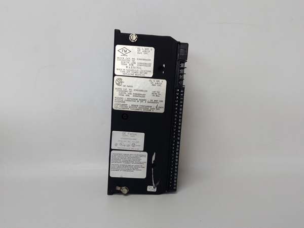
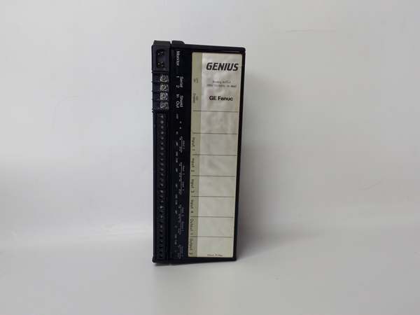
GE IC660BBA100
The Real-World Problem It Solves
The IC660BBA100 solves the challenge of distributed analog signal processing in environments where AC power is readily available and separate DC power supplies would be impractical or costly. Traditional analog I/O modules often require dedicated DC power sources, increasing system complexity and installation costs in field locations. This AC-powered block directly utilizes existing plant power infrastructure, eliminating the need for additional DC power supplies and associated wiring. The five programmable ranges accommodate various sensor and transmitter types without additional signal conditioning hardware, while configurable filtering and advanced diagnostics improve signal integrity and enable predictive maintenance. The 1500V isolation and common mode rejection ensure reliable operation in electrically noisy industrial environments.
Where you’ll typically find it:
- Process Manufacturing Facilities: Connecting 4-20mA transmitters (pressure, temperature, flow, level) and controlling valve positioners across plant locations where 115VAC power is standard.
- Food and Beverage Processing: Analog sensor monitoring and setpoint control for mixing, blending, and packaging equipment with AC-powered field enclosures.
- Pulp and Paper Mills: Analog feedback from position sensors and speed references for conveyor drives, dryer sections, and paper machine actuators.
- Building Automation Systems: Temperature, humidity, and pressure monitoring with analog outputs for HVAC control valves and damper actuators in commercial facilities.
Bottom-line value: Eliminates DC power supply requirements by utilizing existing AC infrastructure, reducing installation costs by up to 40%. Advanced diagnostics enable predictive maintenance, while 1500V isolation and 60dB common mode rejection ensure reliable operation in noisy industrial environments. The five programmable ranges provide flexibility for various analog signal types without additional conditioning hardware.
Hardware Architecture & Under-the-Hood Logic
The IC660BBA100 consists of an Electronics Assembly and a Terminal Assembly. The Electronics Assembly contains the A/D and D/A converters, signal conditioning circuitry, filtering algorithms, AC power conversion, and Genius bus communication hardware. The Terminal Assembly provides screw-type field wiring terminals and status LEDs. Each of the four input circuits converts incoming analog signals to digital values using 12-bit resolution converters with shared scaling circuitry, while the two output circuits use independent 12-bit D/A converters. Configuration data is stored in the Terminal Assembly, enabling hot-swappable Electronics Assembly replacement without reconfiguration. The internal AC power supply provides regulated power for the analog circuits and can drive current mode loads up to 300Ω each.
Internal Signal Flow:
-
AC Power Conversion:
- AC Input: 115VAC power enters through terminals 6 (H) and 7 (N) with a 250V 1/8A slow-blow fuse.
- Power Conversion: Internal power supply converts AC to regulated DC for analog circuits and communication hardware.
- Power Supply Dropout: 10ms dropout time allows ride-through during brief power fluctuations without data loss.
- Power Protection: Internal filtering and protection circuitry provide 10% maximum ripple rejection and protect against transients.
-
Analog Input Processing:
- Signal Reception: Analog voltage or current signal from field device connects to screw terminals on Terminal Assembly.
- Signal Conditioning: Input signal passes through protection circuitry and optional selectable digital filtering (0-1024ms) to reduce noise.
- A/D Conversion: 12-bit + sign ADC converts analog signal to digital count at 4ms intervals.
- Scaling: Digital count is scaled to engineering units using programmable scaling factors (slope/intercept) with optional external scaling resistor for 5V full scale.
- Diagnostic Checking: Diagnostics continuously monitor for underrange, overrange, open wire (current mode), and alarm limits.
- Bus Transmission: Scaled digital data and diagnostic status transmitted over Genius bus to PLC.
- LED Indication: Input status reflected on circuit-specific LEDs (if equipped) and diagnostic messages.
-
Analog Output Processing:
- Digital Reception: Scaled digital output value received from CPU over Genius bus.
- D/A Conversion: 12-bit + sign DAC converts digital count to analog voltage or current signal.
- Signal Conditioning: Output signal passes through protection and current limiting circuitry.
- Load Drive: Signal drives external load (transducer, actuator, valve positioner) up to specified load impedance.
- External Supply Support: For loads exceeding 300Ω, external 24/48VDC supply can be connected for current mode outputs up to 2KΩ.
- Diagnostic Monitoring: Output circuitry monitors for underrange/overrange conditions and load faults.
- Bus Transmission: Output status and diagnostic feedback transmitted to PLC.
- LED Indication: Output status and fault conditions indicated on LEDs and diagnostic messages.
-
Genius Bus Communication:
- Data Exchange: Processed I/O data exchanged with PLC or Bus Controller over serial bus.
- Configuration Updates: Block configuration (scaling, ranges, filters, alarms) can be modified via Hand-Held Monitor without removing block.
- Diagnostics: Comprehensive fault reporting to host enables proactive maintenance.
GE IC660BBA100
Field Service Pitfalls: What Rookies Get Wrong
Incorrect AC Power Connection Without Proper Fusing
The IC660BBA100 requires proper AC power connection with appropriate overcurrent protection, but technicians frequently connect power directly without the specified 250V 1/8A slow-blow fuse or use incorrect fuse ratings. This creates significant fire and equipment damage risks. I’ve seen blocks completely destroyed and adjacent equipment damaged because a technician installed a 10A fuse “to prevent nuisance tripping,” allowing excessive fault currents during a short circuit.
- Field Rule: Always install the specified 250V 1/8A slow-blow fuse in series with the AC power connection at terminals H (6) and N (7). Never bypass or substitute with higher-rated fuses. Use fuse holders designed for the application and ensure proper voltage ratings. Verify fuse operation during commissioning by simulating a fault condition.
Neglecting External Supply Requirements for High-Impedance Loads
The internal power supply can drive current mode loads up to 300Ω, but technicians frequently connect higher-impedance loads without external power, expecting the block to function beyond specifications. This causes output clipping, saturation, or complete failure to drive the load. I’ve encountered a valve positioner requiring 750Ω load impedance that never moved from its minimum position because it was connected directly to the block without external power.
- Field Rule: Calculate load impedance requirements before connecting outputs. For current mode loads up to 300Ω, use internal power. For loads 300Ω-2KΩ, connect an external 24/48VDC power supply to the load and use the block’s current sink capability. Measure load resistance with a multimeter during installation to confirm compatibility. Never exceed 2KΩ total load impedance.
Overlooking External Scaling Resistor Applications
The block supports external scaling resistors for custom range configurations (setting 5V full scale, 10-50mA loops), but technicians frequently attempt to configure custom ranges through software scaling alone, unaware that external resistors are required for certain configurations. This results in inaccurate measurements and output signals. I’ve seen a 0-50mA loop configured to read 0-20mA in software, causing the entire system to read 60% of actual current because the external 100Ω scaling resistor was never installed.
- Field Rule: For 5V full scale configuration, install a 1/2W or greater external scaling resistor as specified in the manual. For 10-50mA current loops, install a 100Ω 1W external scaling resistor. Always verify scaling accuracy with a precision calibrator after installation. Document all external resistor values and configurations for future reference.
Improper AC Grounding and Bonding
The AC-powered block requires proper grounding and bonding for safety and noise immunity, but technicians frequently rely solely on the equipment ground conductor without considering the grounding implications of AC power in distributed I/O systems. This creates ground loops, common mode noise issues, and safety hazards. I’ve measured ground loop currents of several amperes between blocks installed in different enclosures with different earth references, causing measurement errors and diagnostic false alarms.
- Field Rule: Follow AC grounding best practices strictly. Ensure proper grounding of the block’s ground terminal to the main panel earth ground. Use single-point grounding for the Genius I/O system to avoid ground loops. Verify ground resistance is less than 1Ω between the block ground terminal and the main earth ground. In distributed systems, consider isolated ground or technical ground configurations to minimize ground loops.
Misunderstanding Power Supply Dropout Implications
The 10ms power supply dropout time provides ride-through during brief power fluctuations, but technicians frequently assume this means the block can operate indefinitely during power outages or that it will maintain outputs for extended periods. This leads to inappropriate reliance on the dropout capability during planned or extended power interruptions. I’ve seen processes go out of control because technicians assumed outputs would hold during generator transfer times exceeding the 10ms capability.
- Field Rule: Understand that 10ms dropout provides only brief ride-through for momentary power fluctuations (one AC cycle), not extended power interruptions. Configure output behavior (hold last state vs. go to default) based on process safety requirements. For applications requiring extended hold times during power outages, implement UPS systems or battery backup for critical control loops. Test power transfer scenarios during commissioning to verify correct system behavior.
Neglecting AC Power Quality Considerations
AC-powered analog blocks are susceptible to power quality issues such as voltage sags, swells, harmonics, and transients, but technicians frequently ignore power quality during installation and commissioning. Poor power quality can cause measurement errors, communication failures, and premature component failure. I’ve encountered systems with ±15% voltage fluctuations causing measurement drift of 2-3% and frequent communication errors that disappeared after installing power conditioning equipment.
- Field Rule: Measure power quality at the installation site before commissioning using a power quality analyzer. Ensure voltage remains within 98-132VAC range with minimal harmonics and transients. Install power conditioning equipment (line conditioners, surge protectors, UPS) if power quality is marginal. Monitor power quality during operation to detect degradation or issues affecting performance. Document baseline power quality measurements for future comparison.
Disabling Diagnostics to Eliminate Nuisance Alarms
Advanced diagnostics (underrange, overrange, open wire, high/low alarms) provide early fault detection but technicians frequently disable them to eliminate nuisance alarms during commissioning without addressing root causes. This disables valuable predictive maintenance capabilities and allows faults to develop undetected until system failure occurs. I’ve seen a flow control system overdose chemicals due to a failed 4-20mA transmitter that went undetected because open wire diagnostics were disabled to eliminate false alarms during startup.
- Field Rule: Keep all diagnostics enabled and properly configure alarm thresholds to eliminate nuisance alarms rather than disabling features entirely. Use commissioning to identify actual alarm conditions and adjust thresholds to appropriate values. Monitor diagnostic events closely during operation to identify trends indicating developing faults before they cause system failures. Document all diagnostic configurations and threshold values for future reference.
Commercial Availability & Pricing Note
Please note: The listed price is for reference only and is not binding. Final pricing and terms are subject to negotiation based on current market conditions and availability. As an Emerson product (acquired from GE Intelligent Platforms), this block may be subject to specific OEM distribution agreements. Remanufactured units may offer cost savings with warranty coverage, but availability and lead times vary significantly based on stock levels. Verify compatibility with your Genius I/O system and AC power requirements before purchasing.


