
Description
Hard-Numbers: Technical Specifications
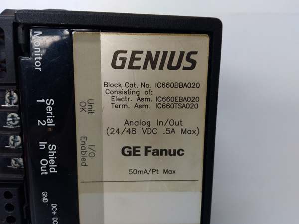
- Input Channels: 4 independent analog inputs
- Output Channels: 2 independent analog outputs
- Analog Ranges: 0-10 VDC, ±10 VDC, ±5 VDC, 0-5 VDC, 4-20 mA / 1-5 VDC
- Power Supply Voltage: 24/48 VDC nominal
- Operating Voltage Range: 18-56 VDC
- Power Consumption: 8W maximum
- Heat Dissipation: 6W
- I/O Resolution: 12-bit + sign
- I/O Update Frequency: Once every 4ms
- Input Filter Times: None, 8, 16, 32, 64, 128, 256, 512, 1024ms (selectable)
- Absolute Accuracy (at 25°C): Typical ±0.2% of full scale; Maximum ±0.5% of full scale
- Thermal Drift (from 25°C): Typical 10 PPM/°C; Maximum 40 PPM/°C
- Output Load Capability:
- Voltage mode: 2000Ω or greater
- Current mode: 0-300Ω with internal supply, up to 2KΩ with external supply
- Common Mode Rejection: 60 dB (0-1 KHz)
- Common Mode Voltage: ±170V maximum
- Isolation: 1500V block-to-block isolation
- Input Diagnostics: Underrange, Overrange, High/Low Alarm, Open Wire (current mode)
- Output Diagnostics: Underrange, Overrange
- Status LEDs: Unit OK, I/O Enabled
- Operating Temperature: 0°C to +60°C (32°F to +140°F)
- Storage Temperature: -40°C to +100°C (-40°F to +212°F)
- Humidity Range: 5% to 95% non-condensing
- Vibration: 5-10 Hz at 0.2″ (5.08mm) displacement; 10-200 Hz at 1G
- Dimensions: 8.83″ x 3.50″ x 3.94″ (22.44cm x 8.89cm x 10.00cm)
- Weight: 4 lbs (1.8 kg)
- Bus Compatibility: Genius I/O serial bus protocol, Phase B block (backward compatible)
- Hand-Held Monitor Compatibility: IC66HHM500, IC66HHM501 (configuration change required)

GE IC660BBA020
The Real-World Problem It Solves
The IC660BBA020 solves the challenge of distributed analog signal processing in industrial environments requiring flexibility in signal types and ranges. Traditional centralized analog I/O requires long analog cable runs susceptible to noise interference and signal degradation. This Genius I/O block processes analog signals locally near field devices, converting them to digital signals for transmission over the serial bus. The five programmable ranges accommodate various sensor and transmitter types without additional signal conditioning hardware, while configurable filtering and advanced diagnostics improve signal integrity and enable predictive maintenance. The distributed architecture reduces wiring costs by up to 60% compared to traditional centralized analog I/O systems.
Where you’ll typically find it:
- Process Industries: Connecting 4-20mA transmitters (pressure, temperature, flow, level) and controlling valve positioners across distributed field locations.
- Food and Beverage: Analog sensor monitoring and setpoint control for mixing, blending, and packaging equipment requiring precise temperature and speed control.
- Material Handling: Analog feedback from position sensors and speed references for conveyor drives and automated storage and retrieval systems.
- Water/Wastewater Treatment: Monitoring pH sensors, conductivity probes, and controlling chemical dosing pumps across remote treatment basins and distribution points.
Bottom-line value: Eliminates signal conditioning hardware and reduces analog wiring infrastructure by integrating programmable ranges and distributed intelligence directly in the field module. Advanced diagnostics enable predictive maintenance, while 1500V isolation ensures reliability in electrically noisy industrial environments.
Hardware Architecture & Under-the-Hood Logic
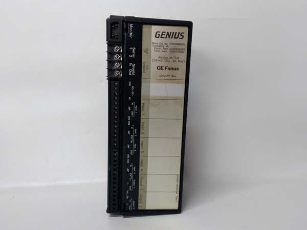
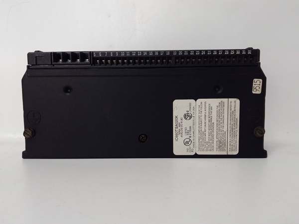
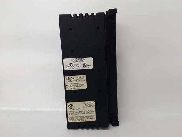
The IC660BBA020 consists of an Electronics Assembly and a Terminal Assembly. The Electronics Assembly contains the A/D and D/A converters, signal conditioning circuitry, filtering algorithms, and Genius bus communication hardware. The Terminal Assembly provides screw-type field wiring terminals and status LEDs. Each of the four input circuits converts incoming analog signals to digital values using 12-bit resolution converters, with selectable scaling to engineering units. The two output circuits convert digital values from the CPU to analog voltage or current signals. Independent power regulation for each output circuit allows simultaneous voltage and current mode operation. Configuration data is stored in the Terminal Assembly, enabling hot-swappable Electronics Assembly replacement without reconfiguration.
Internal Signal Flow:
-
Analog Input:
- Signal Reception: Analog voltage or current signal from field device connects to screw terminals on Terminal Assembly.
- Signal Conditioning: Input signal passes through protection circuitry and optional selectable digital filtering (0-1024ms) to reduce noise.
- A/D Conversion: 12-bit + sign ADC converts analog signal to digital count at 4ms intervals.
- Scaling: Digital count is scaled to engineering units using programmable scaling factors (slope/intercept).
- Diagnostic Checking: Diagnostics continuously monitor for underrange, overrange, open wire (current mode), and alarm limits.
- Bus Transmission: Scaled digital data and diagnostic status transmitted over Genius bus to PLC.
- LED Indication: Input status reflected on circuit-specific LEDs (if equipped) and diagnostic messages.
-
Analog Output:
- Digital Reception: Scaled digital output value received from CPU over Genius bus.
- D/A Conversion: 12-bit + sign DAC converts digital count to analog voltage or current signal.
- Signal Conditioning: Output signal passes through protection and current limiting circuitry.
- Load Drive: Signal drives external load (transducer, actuator, valve positioner) up to specified load impedance.
- Diagnostic Monitoring: Output circuitry monitors for underrange/overrange conditions and load faults.
- Bus Transmission: Output status and diagnostic feedback transmitted to PLC.
- LED Indication: Output status and fault conditions indicated on LEDs and diagnostic messages.
-
Genius Bus Communication:
- Data Exchange: Processed I/O data exchanged with PLC or Bus Controller over serial bus.
- Configuration Updates: Block configuration (scaling, ranges, filters, alarms) can be modified via Hand-Held Monitor without removing block.
- Diagnostics: Comprehensive fault reporting to host enables proactive maintenance.
GE IC660BBA020
Field Service Pitfalls: What Rookies Get Wrong
Incorrect Filter Time Settings for Application Requirements
The IC660BBA020 offers selectable input filter times from 0 to 1024ms in increments, but technicians frequently leave filters at default (none) or set them arbitrarily without considering sensor characteristics and process dynamics. In noisy environments with VFDs, motors, and welding equipment, lack of filtering causes signal fluctuations and false readings. Conversely, setting excessively long filters (512ms or 1024ms) for fast-responding processes creates unacceptable response time delays, causing control loop instability and overshoot. I’ve seen a temperature control system oscillate because the filter was set to 1024ms while the process required response times under 100ms.
- Field Rule: Match filter times to application requirements and noise environment. For fast processes (flow control, high-speed motion), use 0-16ms filters. For moderate processes (temperature, pressure), use 32-128ms. For extremely noisy environments or slow processes (level, batch pH), use 256-512ms. Never set filters longer than the required process response time.
Improper Wiring of Current Loop Inputs
Current mode inputs (4-20mA) require specific wiring configurations to ensure accurate measurement and open wire detection, but technicians frequently wire current sources incorrectly, bypassing the internal sense resistor or creating parallel paths that affect accuracy. I’ve encountered entire measurement systems reading incorrectly because the transmitter was wired across the wrong terminals, causing the internal current sense resistor to be bypassed and the block to read zero regardless of actual signal.
- Quick Fix: For 4-20mA inputs, wire the transmitter positive lead to the I+ terminal and the negative lead to the I- terminal. Ensure the current loop is complete and the internal sense resistor is in series with the loop. Use a multimeter to measure current at the block terminals to verify correct wiring. Enable open wire diagnostics and test with an open circuit to confirm detection functionality.
Neglecting Load Impedance Matching for Current Outputs
Current mode outputs can drive loads up to 300Ω with internal power or up to 2KΩ with external power, but technicians frequently connect loads exceeding these limits without understanding the implications. Exceeding 300Ω on internal power causes the output to clip or saturate, resulting in incorrect control signals and process errors. I’ve seen a valve positioner requiring 500Ω load impedance connected directly to the internal power output, causing the valve to never fully open despite a 20mA command.
- Field Rule: Verify load impedance requirements before connecting outputs. For loads up to 300Ω, use internal power. For loads 300Ω-2KΩ, connect an external 24/48VDC power supply to the load and use the block’s internal current sink capability. Never exceed 2KΩ total load impedance. Measure load resistance with a multimeter during installation to confirm compatibility.
Ignoring Thermal Drift Compensation
The block’s thermal drift specification (typical 10 PPM/°C, maximum 40 PPM/°C) indicates accuracy variations with temperature changes, but technicians frequently ignore this effect during commissioning and calibration. In environments with wide temperature fluctuations (outdoor installations, unheated enclosures), thermal drift can cause measurement errors exceeding 1% of full scale, affecting process control quality. I’ve seen a flow measurement system drift by 3% during seasonal temperature changes, requiring periodic recalibration to maintain accuracy.
- Field Rule: Install blocks in temperature-controlled environments whenever possible (enclosure with heating/cooling). For installations with wide temperature ranges, perform calibration at multiple temperatures or implement temperature compensation in the PLC logic. Monitor diagnostic reports for drift warnings and schedule periodic recalibration based on thermal conditions. Document calibration dates and environmental conditions for reference.
Overlooking Isolation Grounding Practices
The 1500V block-to-block isolation provides protection against ground loops and common mode noise, but technicians frequently connect grounds incorrectly, creating paths that compromise isolation effectiveness. Improper grounding of sensor shields, multiple ground references, or connecting the block ground to different potentials than the PLC ground creates ground loops that introduce noise and measurement errors. I’ve encountered analog measurement systems with ±10% signal fluctuations caused by improper grounding practices that completely negated the isolation benefits.
- Field Rule: Follow isolation grounding best practices strictly. Connect sensor shields only at one end (preferably at the sensor, not the block). Use dedicated ground wires for the block’s ground terminal, not sharing it with other equipment grounds that may carry noise or transient currents. Verify isolation resistance between block ground and other system grounds before energizing. Use isolated power supplies when different ground potentials exist.
Disabling Diagnostics to Eliminate Nuisance Alarms
Advanced diagnostics (underrange, overrange, open wire, high/low alarms) provide early fault detection but technicians frequently disable them to eliminate nuisance alarms during commissioning without addressing root causes. This disables valuable predictive maintenance capabilities and allows faults to develop undetected until system failure occurs. I’ve seen a chemical dosing system overdose due to a failed 4-20mA transmitter that went undetected because open wire diagnostics were disabled to eliminate false alarms during startup.
- Field Rule: Keep all diagnostics enabled and properly configure alarm thresholds to eliminate nuisance alarms rather than disabling features entirely. Use commissioning to identify actual alarm conditions and adjust thresholds to appropriate values. Monitor diagnostic events closely during operation to identify trends indicating developing faults before they cause system failures. Document all diagnostic configurations and threshold values for future reference.
Incorrect Output Default State Configuration
Each output can be configured to hold its last state or go to a default value if CPU communications are lost, but technicians frequently leave this setting at default without considering process safety requirements. This can cause outputs to hold unsafe states during communications failures, creating hazardous conditions or equipment damage. I’ve seen a valve stuck in open position during a PLC power cycle because the output was configured to hold last state instead of going to a safe closed default.
- Field Rule: Configure output behavior for communications loss based on process safety requirements. For fail-safe applications (valves should close on failure), set outputs to go to default (safe) value on communications loss. For applications requiring continued operation, configure outputs to hold last state and ensure backup power systems are in place. Test communications failure scenarios during commissioning to verify correct output behavior.
Commercial Availability & Pricing Note
Please note: The listed price is for reference only and is not binding. Final pricing and terms are subject to negotiation based on current market conditions and availability. As an Emerson product (acquired from GE Intelligent Platforms), this block may be subject to specific OEM distribution agreements. Remanufactured units may offer cost savings with warranty coverage, but availability and lead times vary significantly based on stock levels. Verify compatibility with your Genius I/O system before purchasing.


