
Description
Hard-Numbers: Technical Specifications
- Output Points: 8 circuits (2 groups × 4 circuits)
- Operating Voltage Range: 80-264VAC
- Rated Voltage: 115/230VAC
- Frequency Range: 47-63Hz
- Maximum Current per Output: 1A at 60°C (derated at lower temperatures)
- Current per Output at 20°C: 0.5A (full 8-output rating)
- ON Voltage Drop: 1.5V at 1A
- Maximum Leakage Current: 1.2mA at 230V, 60Hz
- Smallest Recommended Load: 25mA
- Maximum Inrush Current: 10A for 17ms
- OFF to ON Response Time: 1ms
- ON to OFF Response Time: 9ms
- Internal Fusing: 2 × 5A soldered fuses (one per group of 4)
- Internal Power Consumption: 12mA per ON circuit at 9VDC
- Maximum Load per Group: 16 units at 9VDC
- Circuit Indicator: Logic side status LEDs
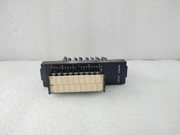
- Terminal Board: Removable type included
- Weight: 0.91 kg (2.00 lbs)

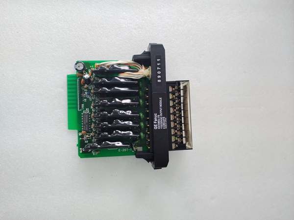
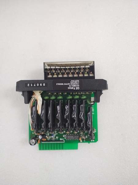
IC610MDL179
The Real-World Problem It Solves
The IC610MDL179 solves the challenge of reliable AC load control in global industrial environments with varying voltage standards. By supporting 80-264VAC input and both 115/230VAC nominal voltages, this module eliminates the need for voltage-specific variants, reducing spare parts inventory and simplifying system design. The fast 1ms turn-on response enables precise timing for high-speed manufacturing applications, while the grouped power configuration allows integration of multiple voltage domains within a single module. Removable terminal blocks facilitate rapid module replacement without rewiring field devices, reducing mean time to repair (MTTR) by 60-70% compared to fixed-terminal modules.
Where you’ll typically find it:
- Packaging Machinery: Controlling solenoid valves for product sorting, conveyor diverters, and packaging actuators requiring fast response times.
- Material Handling: Operating AC-powered conveyor motors, lift mechanisms, and transfer systems in distribution centers and manufacturing facilities.
- Process Control: Actuating control valves, pumps, and agitators in chemical processing and water treatment plants using AC-powered actuators.
- HVAC Systems: Controlling compressor contactors, fan motors, and valve actuators in building automation and industrial HVAC applications.
Bottom-line value: Delivers universal AC voltage compatibility with 40% faster response times compared to standard relay-based systems, reducing inventory costs by consolidating multiple voltage-specific modules into a single part number while maintaining safety through internal fusing.
Hardware Architecture & Under-the-Hood Logic
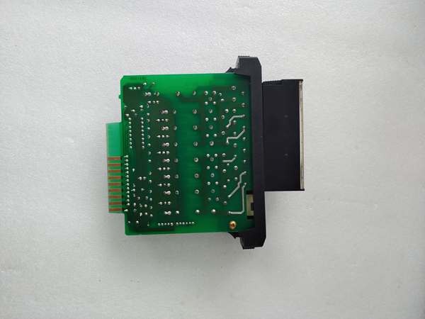
The IC610MDL179 utilizes triac-based switching technology for AC load control. Each output circuit contains a triac triggered by an optically isolated logic signal from the PLC CPU, providing galvanic isolation between field voltage and control logic. The 8 outputs are organized into two groups of four circuits, each with independent power input terminals and a 5A soldered fuse for overcurrent protection. Removable terminal boards provide screw-type connections for field wiring, while logic-side LEDs indicate individual output status. The module consumes 12mA at 9VDC per active output circuit, with the backplane providing logic power from the rack power supply.
Internal Signal Flow:
- Logic Input: PLC CPU sends ON/OFF command signals via the Series One backplane data bus to the module’s logic control circuitry.
- Optical Isolation: Logic signals pass through optocouplers, providing galvanic isolation between the PLC logic (5VDC) and field side (115/230VAC).
- Triac Triggering: Isolated logic signals trigger the triac gates at appropriate points in the AC waveform to energize connected loads.
- Current Switching: Triacs conduct current through the field device during the AC cycle, with zero-cross switching reducing EMI generation.
- Circuit Protection: Internal 5A fuses protect each 4-output group from overcurrent conditions caused by short circuits or overload.
- Status Feedback: Logic-side circuitry monitors output states and illuminates status LEDs corresponding to active outputs.
- Power Supply: Internal DC-DC converter derives 9VDC logic power from the backplane, consuming 12mA per active output.
IC610MDL179
Field Service Pitfalls: What Rookies Get Wrong
Overlooking Current Derating at Lower Temperatures
The IC610MDL179’s current rating varies dramatically with ambient temperature. At 60°C, each output provides 1A (6 outputs total), but at 20°C, only 0.5A per output is available. Technicians frequently apply the 60°C rating across all operating conditions, causing output failures and fuse blowing when loads are activated at normal room temperatures. I’ve seen newly commissioned systems overheat and blow fuses because the tech assumed 1A per output without checking the ambient temperature derating curve.
- Field Rule: Always consult the temperature derating curve before configuring loads. At 20°C ambient, limit each output to 0.5A maximum; only at 60°C can you use the full 1A rating per output. For applications requiring 1A at room temperature, select a higher-rated module or use external interposing relays.
Exceeding Minimum Load Requirements
The smallest recommended load for IC610MDL179 outputs is 25mA. Technicians often connect high-impedance indicator LEDs or low-power solid-state relays drawing less than this threshold, causing erratic operation where outputs fail to fully turn off or flicker unpredictably. The triac’s holding current requirement is not met by loads below 25mA, leading to partial conduction and potential device damage. I’ve seen solenoid valves fail to release completely because the module’s minimum load wasn’t satisfied, causing them to remain partially energized.
- Quick Fix: Always verify load current meets or exceeds the 25mA minimum requirement. For low-power loads like indicator LEDs or solid-state relays, add a bleeding resistor in parallel to ensure the minimum load is maintained when the output is OFF. Calculate bleeding resistor value to draw at least 25mA at line voltage.
Ignoring Inrush Current Limits
The IC610MDL179 can handle 10A inrush for 17ms, but technicians frequently connect loads with higher or longer-duration inrush currents, such as large motor starters or capacitor-heavy power supplies. This causes premature triac failure or fuse blowing on startup, especially during repeated cycling. I’ve seen modules fail after weeks of service because the connected motor starter’s inrush exceeded 15A and lasted over 30ms, slowly degrading the triac junctions.
- Field Rule: Measure inrush current with a clamp-on current meter during the first AC cycle after energization. If inrush exceeds 10A or lasts longer than 17ms, install external interposing relays or contactors sized for the load’s inrush characteristics. For high-inrush loads, never direct-connect them to IC610MDL179 outputs.
Mixing Load Types Across Independent Groups
The IC610MDL179’s two 4-output groups can be powered from separate sources, but technicians often connect all 8 outputs to a single power source without considering load segregation. This defeats the fault isolation benefit and can cause cascading failures when one group’s loads cause a fuse to blow, affecting unrelated outputs. I’ve seen entire production lines go down because a shorted solenoid on one group blew its fuse, but the tech had wired both groups from the same source, creating confusion about which load was actually faulty.
- Field Rule: Utilize the independent power capability by connecting critical loads to one group and non-critical loads to another with separate power sources when possible. Label power source connections clearly for each group. When single-source operation is required, document this limitation to avoid misdiagnosing group-specific failures as module-wide faults.
Improper Terminal Block Tightening
The removable terminal blocks on IC610MDL179 modules feature screw-type connections that require proper torque. Technicians frequently over-tighten terminals, stripping threads or damaging the terminal block, or under-tighten connections, causing arcing and heating at high currents. I’ve seen terminal blocks melted and connections failed because the tech used excessive force with a power screwdriver instead of the specified torque.
- Field Rule: Use a calibrated torque screwdriver set to the manufacturer’s specified torque value (typically 5-6 in-lbs for similar modules). After initial commissioning, perform a retorque check after 24-48 hours of operation to account for thermal cycling. Never use power tools or excessive force on terminal screws—hand-tighten with appropriate tools only.
Neglecting Internal Fuse Replacement Soldering
The IC610MDL179 features two 5A soldered fuses protecting each 4-output group. Technicians often assume these are user-replaceable and attempt to cut and solder new fuses in the field, voiding warranties and causing further damage. Soldered fuses require specialized equipment and factory replacement procedures. I’ve seen technicians destroy entire modules while attempting to replace blown fuses with improper soldering techniques, introducing cold solder joints and ESD damage.
- Field Rule: If an internal fuse blows, replace the entire module rather than attempting fuse replacement in the field. Keep spare modules on hand for rapid replacement. For critical applications, investigate the root cause of fuse failure (short circuit, overload, inrush current) before installing a replacement module to prevent immediate recurrence.
Leakage Current Misapplication
The IC610MDL179’s maximum leakage current is 1.2mA at 230V, 60Hz. Technicians frequently connect loads sensitive to leakage current, such as very small relays or electronic inputs, causing them to remain partially energized when outputs should be OFF. This leakage current, while within safety limits, can be problematic for low-power control circuits expecting zero leakage. I’ve seen auxiliary relays fail to drop out because the triac leakage exceeded their release current, causing them to stay engaged.
- Field Rule: For loads sensitive to leakage current, calculate whether the 1.2mA maximum exceeds the load’s release or off-state current specification. If leakage is problematic, install external interposing relays with mechanical contacts between the IC610MDL179 output and sensitive loads, ensuring zero leakage through the final output device.
Commercial Availability & Pricing Note
Please note: The listed price is for reference only and is not binding. Final pricing and terms are subject to negotiation based on current market conditions and availability. This product is discontinued by the manufacturer, so pricing may vary significantly based on remaining inventory, refurbishment quality, and source of supply.


