
Description
Hard-Numbers: Technical Specifications
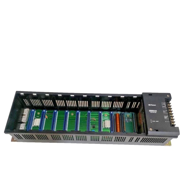
- Slot Capacity: 10 module slots
- Input Voltage: 20.5 to 30VDC (100% capacity used)
- Input Voltage (Partial Load): 18 to 30VDC (90% capacity used)
- Voltage Ripple: ≤10% of input voltage
- Output Currents: +5VDC (1.4A), +9VDC (1.7A), +24VDC (0.5A)
- Total Output Power: Max 2.9A across all voltages
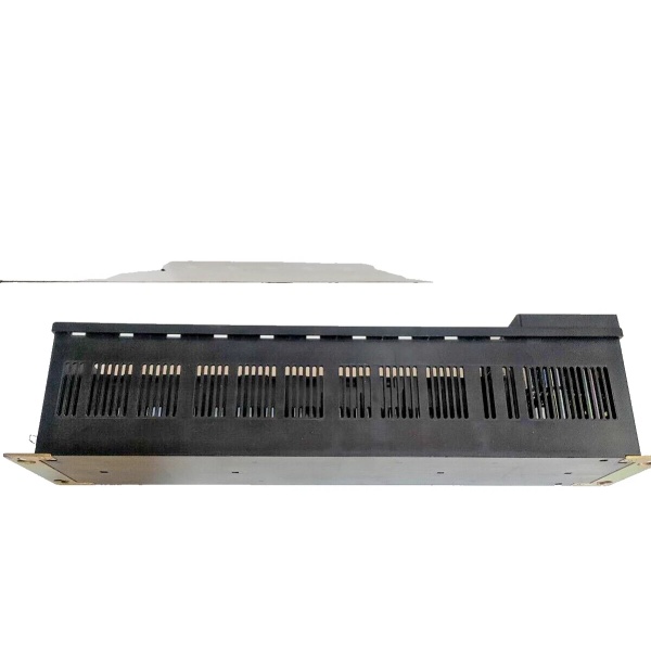
- Environmental Rating: Humidity 5% to 95% non-condensing
- Operating Temperature: 0°C to +60°C (32°F to +140°F)
- Weight: 3 lbs 2.1 oz (1.4 kg)
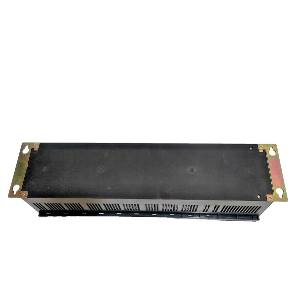
- Dimensions: 5.0″ x 5.0″ x 17.0″ (12.7 cm x 12.7 cm x 43.2 cm)
- Expandability: Non-expandable, fixed 10-slot configuration
- Certifications: UL Listed, MIL STD 810C compliant, NEMA ICS3-304 noise immunity

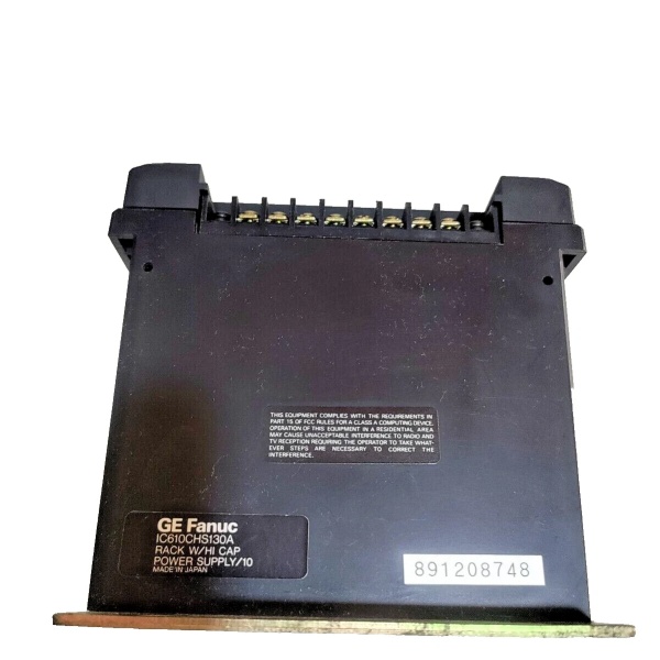
GE IC610CHS130A
The Real-World Problem It Solves
The IC610CHS134A solves the challenge of PLC system integration in DC-powered environments. Many industrial sites, particularly mining, marine, and mobile equipment applications, operate exclusively on 24VDC power to avoid AC voltage risks and simplify power distribution. The rack eliminates the need for external AC-to-DC converters, reducing failure points and installation complexity. With vibration resistance meeting JIS C 0911 IIB Class 3 standards, it operates reliably in heavy equipment environments where standard AC-powered racks would fail prematurely from mechanical stress.
Where you’ll typically find it:
- Mobile Equipment: Installed in large mining trucks, heavy construction machinery, and port cranes where DC power is standard.
- Marine Systems: Used in vessel control panels where DC power distribution is preferred for safety and redundancy.
- Offshore Platforms: Deployed in drilling platform control systems where AC power sources may be unavailable or hazardous.
- Rail Transportation: Integrated into train control systems requiring vibration-resistant DC-powered PLC racks.
Bottom-line value: Delivers 24VDC PLC system integration with 3x longer operational life in high-vibration environments compared to AC-powered racks, reducing maintenance costs by over 60% in mobile and marine applications.
Hardware Architecture & Under-the-Hood Logic
The IC610CHS134A integrates a 24VDC power supply within a 10-slot rack structure. DC input power (20.5-30VDC) enters via screw terminals and is conditioned by the internal power supply to provide stable 5VDC for CPU logic, 9VDC for module electronics, and regulated 24VDC for field devices. The rack supports up to 10 I/O modules, with backplane connectors facilitating parallel data communication between modules. Vibration-resistant design features include reinforced module retention clips and shock-absorbing mounting brackets that meet MIL STD 810C standards for high-stress environments.
Internal Power Distribution Flow:
- DC Input Stage: 20.5-30VDC power enters via screw terminals with overload protection circuitry.
- Power Conditioning: Input voltage is stabilized and filtered to limit ripple voltage to ≤10% of input.
- Voltage Conversion: Switching regulators generate +5VDC for CPU logic power, +9VDC for module electronics, and regulated 24VDC for field devices.
- Backplane Distribution: Regulated voltages are distributed across the backplane power bus to all installed modules via slot connectors.
- Status Monitoring: LED indicators reflect input power presence, output voltage status, and fault conditions for quick diagnostic assessment.
- Grounding: Chassis ground connects through mounting hardware, providing safety ground and noise reference for the entire assembly.
GE IC610CHS130A
Field Service Pitfalls: What Rookies Get Wrong
Misapplying Voltage Requirements
Technicians frequently attempt to connect 115/230VAC power sources directly to the DC-only IC610CHS134A rack. This damages the internal power conversion circuitry and can destroy installed modules. The rack’s 24VDC input connector may physically accept AC power plugs, leading to accidental misconnection if proper precautions aren’t taken. I’ve seen several racks destroyed due to AC power applied to DC terminals, requiring full replacement and causing days of downtime.
- Field Rule: Always verify input voltage requirements before applying power to the IC610CHS134A. Label the DC input terminals clearly with “24VDC ONLY” warnings to prevent accidental AC connection. Use DC power sources with stable output (ripple ≤5% recommended) to ensure reliable operation.
Neglecting Ripple Voltage Limits
The IC610CHS134A’s voltage ripple limit is specified at ≤10% of input voltage, but technicians often use unregulated DC power supplies that exceed this limit. Excessive ripple voltage can cause communication errors between modules, intermittent resets, and premature component failure. I’ve seen systems crash randomly because the power supply ripple exceeded 20%, causing module logic gates to oscillate incorrectly.
- Quick Fix: Always use regulated DC power supplies with ripple voltage ≤5% when powering the IC610CHS134A. Measure ripple voltage at the rack input terminals with an oscilloscope during commissioning to ensure compliance with specifications. If ripple exceeds limits, add external filtering or replace the power supply.
Mounting Without Vibration Protection
While the IC610CHS134A is designed for high-vibration environments, technicians often mount it directly to rigid surfaces without additional vibration isolation. This voids the vibration resistance rating and can cause module disconnection or backplane damage over time. I’ve seen modules ejected from slots during equipment operation because the rack was mounted without the included shock-absorbing brackets.
- Field Rule: Always use the included shock-absorbing mounting brackets when installing the IC610CHS134A in mobile or high-vibration applications. Verify vibration compliance by performing shake tests according to JIS C 0911 standards after installation. Ensure module retention clips are fully engaged for each installed module to prevent ejection during shock events.
Overlooking Input Voltage Range Limitations
The IC610CHS134A has strict input voltage ranges depending on load capacity. Technicians often operate the rack at full capacity with input voltages below the 20.5VDC minimum, causing voltage drop across modules and unreliable operation. I’ve seen systems go into low-power mode randomly because the input voltage dropped below 20VDC when all modules were active, leading to process interruptions.
- Field Rule: Maintain input voltage ≥20.5VDC when operating the rack at full 10-slot capacity, and ≥18VDC at 90% capacity. Install voltage monitoring relays to trigger alarms when input voltage approaches minimum thresholds. For applications with potentially variable input voltage, include surge protection and voltage regulation at the power source.
Improper Grounding Practices
DC-powered racks have unique grounding requirements compared to AC racks, but technicians often apply AC grounding practices to DC systems. This can create ground loops that cause communication interference, erratic module behavior, and potential safety hazards. I’ve seen Series One systems experience input/output mapping errors because the DC rack was grounded differently than the AC-powered control system it connected to.
- Field Rule: Use single-point grounding for DC-powered racks, connecting only the chassis ground to the main DC ground bus. Avoid connecting the rack to both DC ground and AC safety ground, which creates ground loops. Install isolation transformers between DC racks and AC-powered equipment to eliminate ground loop currents.
Commercial Availability & Pricing Note
Please note: The listed price is for reference only and is not binding. Final pricing and terms are subject to negotiation based on current market conditions and availability. This product is discontinued by the manufacturer, so pricing may vary significantly based on remaining inventory and refurbishment status.


