
Description
Hard-Numbers: Technical Specifications
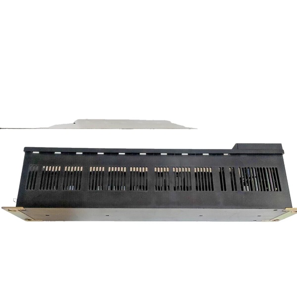
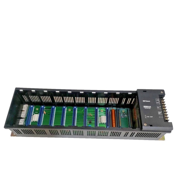
- Slot Capacity: 10 module slots
- Input Voltage: 115/230 Volts AC (47-63 Hz)
- DC Output: 24 Volts DC supported
- Fuse Protection: 2 Amps
- Power Supply Type: High-Capacity integrated supply
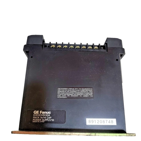
- Terminal Type: Screw-type connections
- Status Indicators: LED status indicators included
- Weight: 2.00 lbs (0.91 kg) / 1.5 kg (varies by source)
- Dimensions: 6.0 in x 5.0 in x 7.0 in (15.2 cm x 12.7 cm x 17.8 cm)
- Operating Temperature: 0°C to +60°C
- Humidity Range: 5% to 95% non-condensing
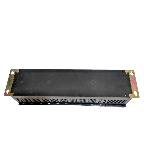
- Mounting: Standard 19-inch cabinet rails, console mounting supported
- Color: Black finish
- Country of Manufacture: Japan

GE IC610CHS130A
The Real-World Problem It Solves
The IC610CHS130A solves the challenge of compact PLC system deployment in space-constrained industrial environments. Traditional PLC racks often required separate power supplies, mounting hardware, and extensive cabinet space. This rack integrates a high-capacity power supply within a 54 square inch footprint—smaller than four 4-pole relays—enabling dense installation in machine enclosures, control panels, and retrofit applications. The dual-voltage input capability eliminates supply voltage compatibility concerns across different global installations, reducing spare parts inventory requirements.
Where you’ll typically find it:
- Machine Tool Retrofitting: Installed in CNC milling machines, lathes, and grinding machines requiring compact PLC control upgrades without extensive cabinet modifications.
- Packaging Machinery: Deployed in high-speed packaging lines where panel space is at a premium and process control needs exceed basic relay logic capabilities.
- Water Treatment Systems: Used in local control cabinets for pump stations and filtration units where Series One controllers manage discrete I/O and simple analog functions.
- Material Handling: Integrated into conveyor control systems and automated storage/retrieval units requiring multiple I/O modules in compact enclosures.
Bottom-line value: Delivers integrated power and mounting infrastructure in less than 10 square feet of panel space, reducing cabinet costs by 30-40% compared to modular rack-plus-power-supply architectures while supporting up to 64 I/O points in a single compact assembly.
Hardware Architecture & Under-the-Hood Logic
The IC610CHS130A serves as both mechanical platform and power distribution hub for Series One PLC systems. The rack houses a high-capacity power supply that accepts 115-230VAC input and generates regulated 5VDC for CPU modules and 24VDC for I/O modules and field devices. The backplane provides parallel data bus connectivity between all installed modules, with each slot offering access to power rails and communication pathways. Screw-type terminal blocks facilitate secure field wiring connections, while LED status indicators provide real-time power and operational status visibility. The integrated 2-amp fuse protects against overload conditions, and the chassis ground connection ensures proper grounding through mounting hardware.
Internal Power Distribution Flow:
- AC Input Stage: Line voltage (115/230VAC) enters through protected screw terminals, with fuse protection at the input stage.
- Primary Conversion: AC input is transformed and rectified to intermediate DC voltage levels by the integrated power supply module.
- Secondary Regulation: Switching regulators generate stable 5VDC for CPU/logic power and 24VDC for I/O module field power.
- Backplane Distribution: Regulated voltages are distributed across the backplane power bus to all installed modules via slot connectors.
- Status Monitoring: LED indicators reflect input power presence, DC output status, and fault conditions for quick diagnostic assessment.
- Grounding: Chassis ground connects through mounting hardware, providing safety ground and noise reference for the entire assembly.
GE IC610CHS130A
Field Service Pitfalls: What Rookies Get Wrong
Ignoring Power Supply Capacity Limits
Technicians frequently overload the IC610CHS130A by installing too many current-drawing modules without calculating total power draw. The high-capacity power supply has limits, and exceeding them causes intermittent failures, voltage sag on the 24VDC bus, or complete shutdown. I’ve seen systems crash mysteriously during peak load cycles—like when all output modules fire simultaneously—because the tech never accounted for worst-case power consumption.
- Field Rule: Always calculate total module power consumption before installation. Sum the 5VDC and 24VDC requirements of all installed modules and verify they remain below the power supply’s rated capacity. Leave at least 20% headroom for inrush currents and future expansion. If power consumption approaches limits, add a supplemental external power supply or redistribute modules across multiple racks.
Improper Grounding Through Mounting Hardware
The IC610CHS130A relies on mounting hardware for chassis ground connection, but technicians often install racks on painted surfaces or use non-conductive mounting hardware without adding supplemental ground straps. This creates floating ground conditions that cause erratic module behavior, communication errors, and increased susceptibility to EMI. I’ve seen Series One systems exhibit random input flickering and output failures because the rack wasn’t properly bonded to the cabinet ground.
- Quick Fix: Ensure solid metal-to-metal contact between rack mounting tabs and cabinet. Scrape paint from mounting surfaces or use star washers to penetrate coatings. Install a supplemental ground wire from rack ground stud to cabinet ground bus, especially when using plastic mounting hardware or installing on painted surfaces. Verify continuity from rack chassis to cabinet ground with a multimeter before applying power.
Hot-Swapping Modules in Powered Racks
Despite the modular design, the IC610CHS130A is not designed for hot-swapping. Technicians frequently insert or remove modules while power is applied, causing backplane damage, module destruction, or electrical arcing. The sudden connection or disconnection of power and data pins creates current surges that can damage adjacent modules. I’ve witnessed entire rack failures after a tech tried to quickly replace a defective output module without shutting down the system.
- Field Rule: Always de-energize the rack before installing or removing any module. Switch off input power, verify voltage absence at the power terminals with a multimeter, and wait at least 30 seconds for DC bus capacitors to discharge. Never force modules into or out of slots—if resistance is felt, verify proper alignment and check for bent pins before attempting insertion.
Neglecting Environmental Operating Limits
Technicians often install IC610CHS130A racks in enclosures that exceed the specified operating temperature range or humidity limits. Compact installations in machinery housings can experience ambient temperatures well above 60°C, causing premature power supply capacitor failure or module thermal shutdown. Similarly, installations in uncontrolled environments may experience condensation that corrodes terminal connections and backplane contacts.
- Field Rule: Verify enclosure environmental conditions meet specifications before installation. Use temperature monitoring in the cabinet and install cooling fans or ventilation if ambient temperatures exceed 50°C. Ensure proper cabinet sealing to prevent moisture ingress, and use desiccant packs in humid environments. For outdoor or harsh environment installations, consider environmental control or NEMA 4X enclosures with appropriate thermal management.
Overlooking LED Status Indicator Diagnostics
The IC610CHS130A includes LED status indicators that provide immediate diagnostic information, but novice technicians often ignore them or misinterpret their meaning. Different LED patterns indicate specific fault conditions, and understanding these patterns can dramatically reduce troubleshooting time. I’ve seen techs spend hours chasing phantom issues while the power supply LED was flashing a code indicating input voltage undervoltage.
- Field Rule: Familiarize yourself with all LED indicator patterns and their meanings before troubleshooting begins. Document the LED state during power-up and normal operation for reference. When faults occur, note the LED pattern immediately—flashing frequencies, colors, and combinations all convey specific diagnostic information. Always consult the Series One manual for detailed LED code interpretation rather than guessing.
Commercial Availability & Pricing Note
Please note: The listed price is for reference only and is not binding. Final pricing and terms are subject to negotiation based on current market conditions and availability.


