
Description
Hard-Numbers: Technical Specifications
- Input Channels: Up to 6 or 12 thermocouples (variant-dependent)
- Supported Thermocouple Types: Type K, Type J
- Input Range: -10 mV to +50 mV
- Output Signal: 0–10 VDC or 4–20 mA (configuration-dependent)
- Output Load Resistance: ≤500 Ω
- Accuracy: ±0.25%
- Signal Conditioning: Low-pass filtering
- Input Impedance: >1 MΩ
- Operating Temperature: -40°C to +70°C (-40°F to +158°F)
- Storage Temperature: -55°C to +85°C (-67°F to +185°F)
- Relay Contact Rating: 24 VDC / 0.5 A
- Power Supply Requirement: +24 VDC
- Power Consumption: <5 W
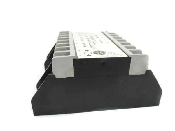
- Board Size: 2.8 cm high x 8.6 cm
- Weight: 0.45 kg (1.0 lbs)
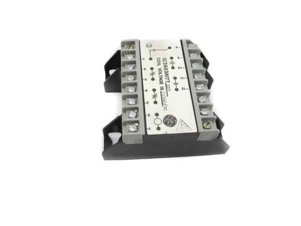
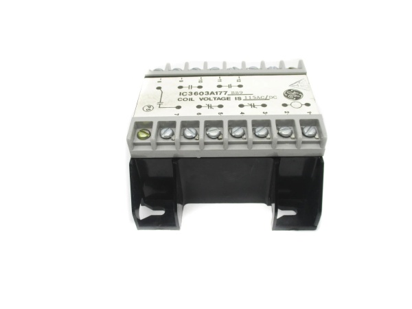
- Configuration Interface: 18 toggle switches (3 rows × 6 switches)

GE IC3603A-277A
The Real-World Problem It Solves
The IC3603A-277A eliminates thermal measurement inaccuracies and false trips caused by single-point sensor failures or localized hot spots in turbine exhaust systems. By mathematically averaging multiple thermocouple inputs, it provides a representative overall temperature reading for the control system, filtering out noise and preventing nuisance alarms from individual sensor drift. Without this module, turbines would rely on single-point temperature data that could trigger unnecessary load reductions or fail to detect genuine overheating conditions due to sensor placement limitations.
Where you’ll typically find it:
- Gas Turbine Exhaust Temperature Monitoring: Installed in Mark II control cabinets, processing exhaust thermocouple arrays (typically 12-16 TCs distributed around the turbine exhaust) to provide averaged TTXM for control and protection.
- Bearing Temperature Surveillance: Averaging multiple bearing thermocouples or RTDs to detect overall bearing health trends rather than reacting to single-point anomalies or sensor noise.
- Combustion Chamber Temperature Monitoring: Processing thermocouple inputs from multiple combustion chambers in heavy-duty gas turbines to ensure balanced combustion and detect hot spots or flame instability.
Bottom-line value: Provides fault-tolerant thermal monitoring by averaging redundant sensors, ensuring the control system sees accurate representative temperatures rather than skewed data from failed or drifting individual thermocouples—critical for preventing both false trips and missed overheating events.
Hardware Architecture & Under-the-Hood Logic
The IC3603A-277A is an analog signal conditioning module designed to accept multiple millivolt-level thermocouple inputs and produce a single averaged analog output. It contains precision summing amplifiers, cold-junction compensation circuits, and low-pass filtering stages. The 18 toggle switches configure which input channels are active, select thermocouple type (Type K vs. Type J), determine averaging method (simple arithmetic mean vs. weighted logic), and set alarm threshold triggers. Internal solid-state relays provide protective shutdown or alarm outputs when averaged temperature exceeds configured setpoints. The module performs signal conditioning including amplification, filtering, and linearization before computing the mathematical average. All processing is analog-based for reliability in harsh turbine environments—no microprocessors or digital logic involved.
Internal Signal Flow:
- Thermocouple Input Reception: Multiple Type K or J thermocouple inputs (typically 6-12 channels) arrive as low-level DC millivolt signals, each representing temperature at a specific measurement point.
- Signal Conditioning & Cold-Junction Compensation: Each input passes through individual conditioning circuits that filter noise, amplify the signal, and apply cold-junction compensation to account for terminal block temperature effects.
- Channel Selection & Configuration: The 18 toggle switches determine which channels are included in the averaging calculation and configure signal processing parameters based on thermocouple type and desired averaging logic.
- Summing & Averaging Circuit: A precision analog summing amplifier adds all active channel signals together, then divides by the number of active channels to compute the arithmetic mean. Weighted averaging may be implemented via resistor networks if configured.
- Output Generation & Relay Logic: The averaged signal is converted to a standard analog output (0-10V DC or 4-20 mA) for transmission to the turbine controller. Simultaneously, comparator circuits monitor the averaged value against thresholds and trigger onboard solid-state relays for alarm or trip outputs when exceeded.
GE IC3603A-277A
Field Service Pitfalls: What Rookies Get Wrong
Misconfigured Toggle Switches During Replacement
The 18 toggle switches on the IC3603A-277A must match the original board’s configuration exactly for proper operation. Rookies frequently install a replacement board without documenting the original switch positions, then guess the configuration based on assumptions about channel count or thermocouple type. Wrong switch settings result in incorrect thermocouple type selection (K vs. J), excluded active channels, or altered averaging logic—causing inaccurate temperature readings that can trip the turbine or mask genuine problems. I’ve seen units load-reject because a new board had Type J selected while the field thermocouples were Type K.
- Field Rule: Before removing any IC3603A-277A, photograph the toggle switch positions from multiple angles to capture all 18 switches. Document the switch pattern (ON/OFF for each of the 3 rows × 6 columns). When installing the replacement, match every switch position exactly—do not “configure based on what you think it should be.” Verify thermocouple type in field against switch settings after installation, using a thermocouple simulator or known temperature source to confirm output accuracy.
Improper Shield Grounding Causing Noise Injection
Thermocouple inputs are millivolt-level signals extremely susceptible to electrical noise. Technicians often ground thermocouple cable shields at both the thermocouple head and the IC3603A-277A terminal block, creating ground loops that inject 50/60Hz noise into the averaging circuit. This causes the averaged temperature reading to fluctuate or read incorrectly, potentially triggering alarms or causing control system instability. The resulting noise-induced oscillation can be difficult to distinguish from actual thermal transients.
- Quick Fix: Ground thermocouple cable shields at a single point only—typically at the control cabinet terminal block or the IC3603A-277A ground terminal, never both. Use shielded twisted-pair thermocouple extension wire conforming to ANSI or IEC standards. Verify shield continuity and isolation from ground at the thermocouple head using a megger or insulation tester. If noise persists, temporarily disconnect individual thermocouple inputs to identify the noisy channel, then inspect its wiring routing for proximity to power cables or VFD outputs.
Ignoring Cold-Junction Compensation Effects
The IC3603A-277A performs cold-junction compensation (CJC) to account for temperature at the terminal block where thermocouple wires connect. Technicians sometimes mount replacement boards in locations with different ambient temperatures than the original, or near heat-generating components, causing CJC errors. A 10°C ambient temperature difference results in a 10°C temperature reading error across all averaged channels—a significant offset for turbine exhaust temperature control that affects load calculations and trip margins.
- Field Rule: Install the IC3603A-277A in the same location as the original board to maintain consistent ambient conditions. Avoid mounting near heat sources such as power supplies, VFDs, or resistor banks. After installation, verify CJC accuracy by injecting a known thermocouple simulator signal at a specific temperature and comparing the module output to the expected value. If offset exists, check board ambient temperature and ensure proper ventilation—do not attempt to “calibrate out” CJC errors by adjusting downstream scaling.
Mixing Thermocouple Types Without Verifying Configuration
Field technicians sometimes replace individual thermocouples in an array with a different type than originally specified (e.g., replacing a Type K with Type J due to parts availability) without reconfiguring the IC3603A-277A toggle switches. Since Type K and Type J thermocouples have different millivolt-per-degree characteristics, the averaging module processes mixed inputs incorrectly, producing a meaningless averaged output that can read high or low depending on the mix ratio. This compromises both control accuracy and protection setpoint integrity.
- Field Rule: Never mix thermocouple types in a single array connected to an IC3603A-277A. If replacing thermocouples, verify the replacement matches the existing type using color coding or markings on the TC extension wire (Type K typically yellow positive, Type J typically white positive in US color codes). Confirm all connected thermocouples match the switch configuration on the module. When in doubt, test each individual thermocouple at a known temperature using a portable thermocouple simulator or calibrator to verify type and output before reconnecting to the module.
Commercial Availability & Pricing Note
Please note: The listed price is for reference only and is not binding. Final pricing and terms are subject to negotiation based on current market conditions and availability.


