
Description
Hard-Numbers: Technical Specifications
- Input Signal Type: Magnetic pickup speed sensor (variable frequency/AC voltage)
- Output Signals: Speed reference voltage, tachometer signal generator output
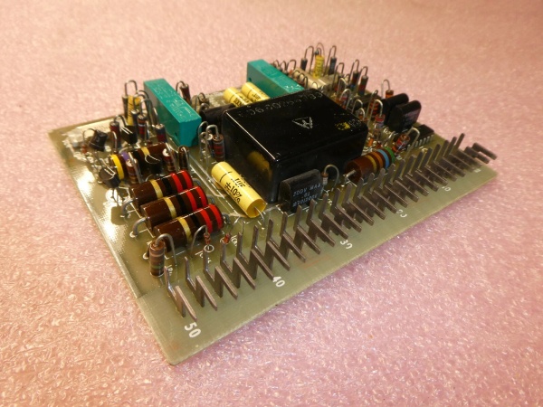
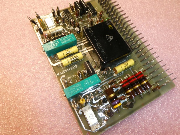
- Adjustment Points: 4 potentiometers (2 blue paired, 2 black)
- Indicator: 1 large red LED (wired to faceplate metal assembly)
- Protection: MOVs (on K variant) for transient voltage suppression
- Circuit Components: Multiple transistors (silver round, black small), 55+ resistors (light blue with color bands)
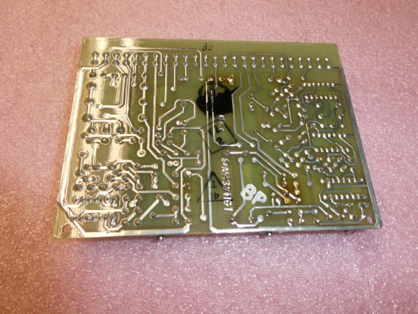
- Connector Type: Edge connector with approximately 50 metal male terminal prongs
- Board Technology: Discrete analog circuit construction
- Power Supply: 28V DC from backplane (Mark I/II standard)
- Operating Temperature: -40°C to +70°C (Mark I/II cabinet rating)
- Weight: Approximately 0.38-0.5 lbs depending on variant
- Dimensions: Standard Mark I/II card form factor
- Calibration: Manual via potentiometer knobs accessed through faceplate

GE IC3600EPSA1
The Real-World Problem It Solves
The IC3600SSZB eliminates the critical failure mode of undetected overspeed or unstable speed reference that causes turbine hunting, load swings, or catastrophic overspeed trips. By providing conditioned speed signals and generating precise reference voltages for the governor loops, it ensures the fuel control system receives accurate speed feedback for droop, isochronous, and load sharing control functions.
Where you’ll typically find it:
- Gas Turbine Control Cabinets: Mounted in Mark I and Mark II Speedtronic racks, directly interfacing with magnetic speed pickups on the turbine accessory gear or generator shaft.
- Steam Turbine Governor Panels: Processing speed signals from turbine shaft-mounted speed sensors for governor valve position control and overspeed protection initiation.
- Mechanical Drive Packages: Installed in compressor or pump drive control systems where precise speed control and indication are critical for process stability and mechanical protection.
Bottom-line value: This board serves as the eyes and reference generator for the governor control system—without its accurate speed processing, the entire fuel or steam valve control system operates blind, risking both operational instability and mechanical overspeed damage.
Hardware Architecture & Under-the-Hood Logic
The IC3600SSZB is a pure analog speed processing board that functions as the primary tachometer interface in Mark I/II control systems. It receives raw speed signals from magnetic pickups (variable frequency AC voltage proportional to shaft speed) and performs signal conditioning, frequency-to-voltage conversion, and reference generation. The board does not contain a microprocessor—all speed processing is handled through discrete analog circuitry including amplifiers, filters, and comparators. The four potentiometers set calibration points for speed matching, gain adjustments, and reference offset values. The large red LED provides local speed indication status, typically illuminating when the board is receiving valid speed signals within operating range. The board interfaces with the system through a 50-pin edge connector that carries the raw speed input, conditioned outputs, and power supply connections.
Internal Signal Flow:
- Speed Input Reception: Raw magnetic pickup signals (AC voltage varying with speed) arrive at the edge connector pins. These signals are typically noisy and vary widely in amplitude.
- Signal Conditioning: The board’s input circuitry filters and amplifies the raw pickup signal, removing noise and normalizing the amplitude for downstream processing. Transistors in this stage provide gain and isolation.
- Frequency-to-Voltage Conversion: Analog circuitry converts the conditioned frequency signal to a proportional DC voltage representing actual turbine speed. This voltage becomes the primary speed feedback signal.
- Reference Generation: Based on potentiometer settings and system operating modes, the board generates reference voltage signals used by governor loops for speed setpoint comparison and load control.
- Output Distribution & Indication: Conditioned speed signals and references exit through the edge connector to governor control cards, start-up sequences, and overspeed protection circuits. The red LED status is driven by a valid-speed detection circuit that illuminates when the processed signal falls within expected speed ranges.
GE IC3600EPSA1
Field Service Pitfalls: What Rookies Get Wrong
Potentiometer Calibration Without Known Speed Reference
Technicians frequently adjust the four potentiometers while attempting to match speed indications or “tune” the board without a known accurate speed reference. This creates calibration drift across multiple channels—the blue paired pots often work together for gain/matching, while the black pots set reference offsets. Adjusting these based on a suspect panel meter or another inaccurate reference creates systematic speed error that affects governor droop settings, load sharing, and overspeed trip calibration. I’ve seen units hunting in parallel operation because one IC3600SSZB was calibrated 2% higher than the other.
- Field Rule: Never adjust speed board potentiometers without either (a) a calibrated tachometer test set injecting known frequency signals, or (b) a verified reference speed source. Document all potentiometer positions (turns from fully counterclockwise) before making any changes. After adjustment, verify speed indication against a trusted reference meter at multiple speed points (low, medium, high operating range).
Ignoring the Red LED Status During Start-Up
The large red LED on the metal faceplate provides critical diagnostic information during turbine start-up sequences. Rookies often overlook this indicator or assume it only indicates “power on.” In reality, this LED typically illuminates only when the board detects valid speed signals within its configured window. During a start-up with no rotation, this LED should be off. If it stays on during zero-speed conditions or fails to illuminate during rotation, you have a pickup wiring issue, board failure, or signal loss. Ignoring this status leads to chasing ghost problems elsewhere in the governor system.
- Quick Fix: Make the red LED status check part of every start-up procedure and troubleshooting walkthrough. Learn your specific unit’s LED behavior pattern—some variants illuminate steady, others pulse. If the LED behavior deviates from the known-good pattern, immediately check magnetic pickup resistance (typically 200-2000 ohms), wiring continuity, and input signal at the edge connector using a multimeter or scope.
Swapping Boards Without Verifying Pickup Polarity and Resistance
A common failure mode after board replacement is incorrect speed indication or reverse speed sensing. This occurs when technicians swap an IC3600SSZB without verifying that the magnetic pickup connections match the expected polarity and that the pickup coil resistance is within specification. Magnetic pickups are polarity-sensitive on some Mark I/II configurations, and a failed pickup can read zero ohms or open circuit. Installing a good board behind a bad or miswired pickup immediately makes the new board appear defective.
- Field Rule: Before installing any replacement IC3600SSZB, measure the magnetic pickup coil resistance at the terminal block and verify against the OEM specification (typically stamped on the pickup itself). Check wiring polarity against the system’s elementary diagram—many Mark II systems use shielded twisted pairs with defined polarity. If the pickup reads open or shorted, troubleshoot the wiring and pickup before condemning the speed control board. A new board will not fix a dead pickup.
Commercial Availability & Pricing Note
Please note: The listed price is for reference only and is not binding. Final pricing and terms are subject to negotiation based on current market conditions and availability.


