
Description
Hard-Numbers: Technical Specifications
- Input Channels: Multiple temperature monitoring channels (configurable via potentiometers)
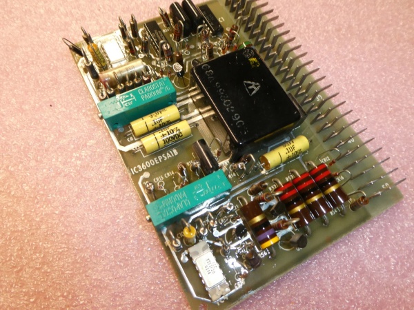
- Adjustment Points: 8 potentiometers (variable resistors) accessible through faceplate
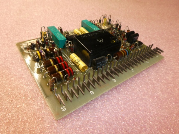
- Circuit Components: 9 transistors (4 silver, 5 black), 55+ resistors, 11 capacitors, 10+ diodes
- Connector Type: 50-pin edge connector (male terminal prongs)
- Weight: Approximately 0.69 lbs (0.31 kg)
- Board Type: Analog signal conditioning and threshold comparison
- Power Consumption: Derived from backplane 24V DC rail
- Calibration Method: Manual adjustment via potentiometer screws through faceplate access holes
- Operating Environment: Industrial turbine control cabinet (vibration-resistant design)
- Protection Logic: Discrete transistor-based comparator circuits for threshold switching
- Status Indication: Logic-level outputs to control system (not field-wired indicators)
- Response Time: Determined by analog circuit time constants (typically sub-second to few seconds)

GE IC3600EPSA1
The Real-World Problem It Solves
The IC3600SOTD1 eliminates the catastrophic risk of undetected thermal runaway in gas and steam turbines by providing multiple, independent temperature trip points. Without this dedicated protection board, a single failed RTD or a drifting temperature sensor could allow critical components—bearings, exhaust temperatures, or internal gas paths—to overheat until mechanical failure occurs, resulting in millions in damage and extended outages.
Where you’ll typically find it:
- Heavy Frame Gas Turbines: Installed in Mark I and Mark II control cabinets monitoring exhaust temperature spreads, bearing temperatures, and lube oil temperatures in Frame 5, Frame 7, and Frame 9 units.
- Steam Turbine Governor Panels: Used to monitor steam chest temperatures, bearing metal temperatures, and condenser hotwell temperatures, providing thermal trips independent of the main governor logic.
- Cogeneration and Combined Cycle Facilities: Protecting heat recovery steam generators (HRSG) and auxiliary equipment where thermal excursions can cause tube failures or heat exchanger damage.
Bottom-line value: This board acts as a hard-wired thermal safety net that protects turbine mechanical assets from heat damage, providing multiple redundant trip points that function even if the main control processor fails or becomes unresponsive.
Hardware Architecture & Under-the-Hood Logic
The IC3600SOTD1 is a purely analog protection board that functions independently of the main turbine control processor. It receives multiple temperature signals (typically from resistance temperature detectors or thermocouples conditioned by other input cards) and compares each against a hard-set reference voltage determined by the eight potentiometers. When a temperature signal exceeds its corresponding threshold, the board’s discrete transistor circuitry switches the output state, triggering a relay or logic signal that initiates a turbine shutdown or alarm sequence. This is not a smart card with programmable logic—its protection behavior is baked into the hardware by the potentiometer settings. The board interfaces with the system through a 50-pin edge connector that carries the temperature inputs, references, and trip output signals to the control rack backplane.
Internal Signal Flow:
- Temperature Signal Reception: Temperature input signals (typically conditioned 4-20mA or voltage signals from other cards) arrive at the edge connector pins. Each input corresponds to one of the protection channels.
- Threshold Reference Generation: Each of the eight potentiometers sets a precise reference voltage level that corresponds to a specific temperature trip point. Turning the potentiometer screw adjusts this reference voltage up or down.
- Analog Comparison: Transistor-based comparator circuits continuously compare the incoming temperature signal voltage against the reference voltage. These are discrete analog comparators, not software comparisons.
- Output Switching: When the temperature signal exceeds the reference voltage, the comparator circuit drives its output transistor to change state. This flips the logic level of the corresponding trip output pin.
- Trip Signal Distribution: The changed output signal travels through the backplane to the master trip relay or control logic, initiating the protective shutdown sequence. The diodes on the board prevent backfeeding and ensure signals only flow in the intended direction.
GE IC3600EPSA1
Field Service Pitfalls: What Rookies Get Wrong
Calibrating Potentiometers Without Validating Reference Temperatures
New technicians often adjust the eight potentiometers based on nameplate temperatures or guesswork without verifying actual trip points. This is dangerous because the relationship between the potentiometer setting and the actual temperature trip value depends on the input signal scaling from upstream cards. If the input card outputs 4-20mA but the over-temp board was calibrated for a 0-10V signal, your trip points will be completely wrong. I’ve seen turbines tripped at normal operating temperatures because a tech turned all the pots fully clockwise “for safety.”
- Field Rule: Never adjust potentiometers without first determining the input signal type and range from the system documentation. Use a calibrated signal simulator to inject a known temperature-equivalent signal and verify the exact trip point for each channel by slowly increasing the signal until the output switches. Document the potentiometer position (turns from fully counterclockwise) and the corresponding trip temperature for each channel.
Ignoring Input Signal Ground Reference Issues
The IC3600SOTD1 compares signals against internal references, but if the input signals share a different ground reference or have ground loops, the trip thresholds become unstable. Technicians chasing erratic temperature trip behavior often overlook ground differentials between the temperature input source cards and the over-temp board. In cabinets with multiple ground references, I’ve seen temperature signals that appear normal on a floating multimeter trigger false trips because the over-temp board sees the ground offset.
- Quick Fix: Verify that all temperature input signals to the IC3600SOTD1 share the same ground reference as the board itself. Check for voltage potential between the input signal ground and the board ground terminal. If you measure more than a few millivolts of offset, trace the grounding scheme and establish a common reference point. Use differential inputs if the configuration allows, or isolate the signal source.
Assuming the Board Provides Local Indication
A common frustration is technicians staring at the IC3600SOTD1 in the rack, expecting LED indicators to show which channel tripped. This board does not have local LEDs or a display—it outputs logic signals to the control system. Rookies waste time troubleshooting the board itself when the real problem is upstream in the control logic that isn’t properly displaying or latching the trip status. The board can be functioning perfectly, but if the HMI or alarm logic is misconfigured, operators won’t know which temperature caused the shutdown.
- Field Rule: Remember that the IC3600SOTD1 is a silent sentinel—its outputs go to the control system, not to local indicators. When troubleshooting a temperature trip, check the control system’s event log, alarm status screens, and input module diagnostics to see which channel changed state. Use a multimeter on the edge connector pins to verify the board is actually switching its outputs when you simulate a temperature exceedance. Don’t assume the board is faulty just because there’s no local indication.
Commercial Availability & Pricing Note
Please note: The listed price is for reference only and is not binding. Final pricing and terms are subject to negotiation based on current market conditions and availability.


