
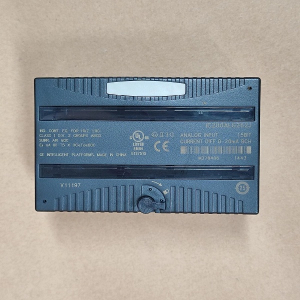
Description
Hard-Numbers: Technical Specifications
- Number of Input Channels: 4 (3-wire and/or 4-wire RTDs, individually isolated)
- Compatible RTD Sensors:
- Platinum: 25, 100, and 1000 ohm
- Copper: 10, 50, and 100 ohm
- Nickel: 100 and 120 ohm
- Nickel/Iron: 604 ohms
- Resistance Input Range: 0-500 ohms; 0-3000 ohms (selectable)
- Resolution: 16 bits (15 bits plus sign)
- Accuracy:
- Resistance measurement: ±0.15% at 25°C
- RTD (temperature) measurement: ±0.15% at 25°C
- Temperature sensitivity (0° to 60°C): ±0.004% of reading; ±1.5µV per °C referred to input
- Update Rate:
- 60 Hz: approximately 210 ms per channel
- 50 Hz: approximately 230 ms per channel
- Frequency Range: 50-60 Hz line frequency
- Isolation:
- Input to Logic: 250V AC continuous
- Input to Frame Ground: 1500V AC for 60 seconds
- Channel to Channel: 50V DC
- Common Mode Rejection: 120 dB at 50-60 Hz
- Normal Mode Rejection: 60 dB at 50-60 Hz
- Power Consumption:
- 5V backplane current: 125 mA maximum
- 3.3V backplane current: 125 mA maximum
- External Power Supply: Not required (module provides RTD excitation current)
- Maximum Lead Resistance: 50 ohms per lead (some sources state 5 ohms; verify with manual)
- Operating Temperature: 0°C to +60°C (32°F to +140°F)
- Diagnostics: Open RTD, input short, underrange, overrange, non-volatile memory storage fault, wiring fault, high/low alarm
- LED Indicators: OK LED (green = backplane power present, amber = module fault, flashing green = boot/update mode)
- Selectable Input Units: Tenths of degrees Celsius, tenths of degrees Fahrenheit, or tenths of ohms
- Compatibility: VersaMax PLC CPU/NIU version 1.10 or higher required

GE IC200ALG331
The Real-World Problem It Solves
This module eliminates the need for separate RTD transmitters and temperature controllers by providing high-precision temperature measurement directly from RTD sensors. The 16-bit resolution and individual channel isolation make it ideal for applications requiring accurate temperature monitoring with immunity to ground loops and electrical noise. The software-configurable resistance/temperature units allow flexible integration into different control systems without additional signal conditioning.
Where you’ll typically find it:
- Chemical process reactors requiring precise temperature control for quality assurance
- HVAC systems monitoring chilled water and heating loop temperatures
- Food processing plants ensuring proper cooking and storage temperatures
- Pharmaceutical manufacturing with strict temperature validation requirements
Bottom line: It’s your precision temperature sensing interface that converts RTD resistance signals into reliable digital data with built-in diagnostics for process safety.
Hardware Architecture & Under-the-Hood Logic
The IC200ALG620-JF is a single-slot VersaMax RTD input module featuring four individually isolated analog input channels, each with a dedicated 16-bit ADC. The module provides excitation current to the RTD sensors and automatically matches the excitation current to each configured RTD type. All conversion and processing is performed on-module, with results transmitted to the CPU or NIU via the VersaMax backplane.
Signal processing breakdown:
- RTD sensor (3-wire or 4-wire configuration) connected to module input terminals
- Module supplies excitation current to RTD based on configured sensor type
- 3-wire or 4-wire connection compensates for lead resistance
- Differential input circuit measures voltage drop across RTD element
- Analog-to-digital converter (16-bit) digitizes measured voltage
- Microprocessor converts resistance value to temperature based on selected RTD type and unit (°C, °F, or ohms)
- Automatic A/D calibration occurs at power-up and repeats periodically to compensate for ambient temperature changes
- Diagnostic circuits detect open RTD, input short, underrange, overrange, wiring faults, and high/low alarm conditions
- Processed temperature/resistance value transmitted as 16-bit word to CPU/NIU via backplane
- OK LED indicates module status; fault conditions reported to PLC for integration into control logic
GE IC200ALG331
Field Service Pitfalls: What Rookies Get Wrong
Exceeding maximum lead resistanceTechs run RTD cables over 200 feet without considering lead resistance. The 50-ohm per lead limit is exceeded, causing readings to drift by several degrees.
- Field Rule: Calculate total loop resistance before installation. Use 4-wire RTDs for long cable runs to compensate for lead resistance. If 3-wire is mandatory, keep runs under 100 feet and use 18 AWG or larger wire.
Mixing 3-wire and 4-wire sensors on the same moduleNew engineers configure Channel 1 with a 3-wire PT100 and Channel 2 with a 4-wire PT1000 without verifying jumper settings. The module detects a wiring fault on one channel and reports inaccurate readings.
- Field Rule: Document the RTD type and wiring configuration for each channel during commissioning. Verify jumper settings on the carrier terminal match the sensor type. Test each channel independently before integrating into control logic.
Forgetting to configure input unitsThe module defaults to tenths of degrees Celsius, but the PLC logic expects tenths of degrees Fahrenheit. Readings appear wrong even though the sensor is functioning correctly.
- Field Rule: Always verify the configured input units match the PLC program expectations. Use consistent units across all channels to avoid confusion during troubleshooting. Document unit settings in your ladder logic comments.
Ignoring open RTD detection in safety-critical loopsRookies disable open RTD detection to avoid nuisance alarms, but this masks failed sensors in safety systems like boiler temperature monitoring.
- Field Rule: Never disable open RTD detection in safety-critical applications. Configure appropriate alarm limits and integrate fault detection into safety logic. Use redundant sensors for critical temperature points if needed.
Improper grounding causing noiseTechs ground RTD shields at both ends, creating ground loops that add 1-2°C error to readings. This is common in panels with VFDs and motor starters.
- Field Rule: Ground RTD cable shields at the I/O module end only for 3-wire sensors. For 4-wire sensors, ground at the sensor end. Use twisted-pair shielded cable and maintain 12-inch minimum separation from power wiring.
Overlooking temperature sensitivity compensationThe module has ±0.004% temperature sensitivity, but installers mount it directly next to heat sources like VFD heat sinks. Ambient temperature swings cause measurement drift.
- Field Rule: Mount RTD modules away from heat-generating equipment. Allow for proper airflow around the module. For high-temperature environments, consider installing temperature compensation routines in the PLC logic.
Please note: The listed price is for reference only and is not binding. Final pricing and terms are subject to negotiation based on current market conditions and availability.


