
Description
Hard-Numbers: Technical Specifications
- Number of Output Channels: 4 individually isolated channels
- Output Signal Range:
- Voltage mode: -10 to +10 VDC (±10 VDC)
- Current mode: 4-20 mA (default), can be configured to 1-20 mA
- Converter Resolution: 16 bits
- Analog Resolution:
- Voltage mode: 381 µV nominal
- Current mode: 381 nA nominal
- Accuracy: ±0.1% maximum of full scale at 25°C; degradation specs not available
- Update Rate: 7 milliseconds maximum
- Common Mode Rejection: 70dB minimum
- Input Impedance: N/A (output module)
- Common Mode Range: N/A (output module)
- Isolation: 250V AC continuous (output to logic/frame ground); 1500V AC for 1 minute
- Output Grouping: Four (4) individually isolated channels
- Power Consumption:
- Backplane current: 10mA @ 5VDC; 115mA @ 3.3V
- External current consumption: 100mA maximum plus load currents
- Inrush current: 2A maximum
- External Supply Voltage Range: +18 to +30VDC including ripple
- Diagnostics: High/Low Limit, Over/Underrange, Open Wire, Loss of Field Power Supply, Non-volatile memory fault
- LED Indicators: OK LED, FLD PWR LED
- Channel Identification (OK LED): On (normal operation), flashing green (boot mode or update), flashing amber (self-diagnostic error)
- Module ID: N/A (output module)

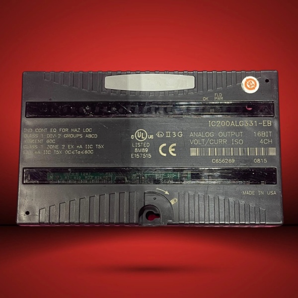
GE IC200ALG331
The Real-World Problem It Solves
This module solves the problem of interfacing PLC systems to analog-controlled devices with high precision and isolation. The 16-bit resolution allows for fine-grained control of process variables, while the software-configurable channels let you mix voltage and current outputs without hardware changes. The individual channel isolation eliminates ground loop issues common in multi-point analog systems, especially when controlling equipment from different power sources.
Where you’ll typically find it:
- Process control applications with multiple control valves requiring independent analog signals
- Motor control systems where 4-20mA outputs adjust VFD speed and torque
- Test and measurement environments needing precise voltage/current output for instrumentation
- Energy management systems driving variable frequency drives for pump control
Bottom line: It’s your high-precision analog output interface for applications where millivolt- and microamp-level accuracy matter.
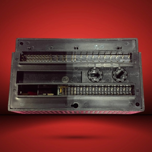
Hardware Architecture & Under-the-Hood Logic
The IC200ALG331 is a single-slot VersaMax analog output module featuring four individually isolated 16-bit D/A converters. It receives analog output data words from the CPU or Network Interface Unit (NIU) via the VersaMax backplane, then converts and outputs the signals in the configured range (voltage or current). All channels are individually isolated for enhanced noise immunity and safety.
Signal flow breakdown:
- Digital output data words (16 bits) received from CPU/NIU via backplane
- Software configuration selects output range (voltage or current) for each channel
- Isolation barrier protects logic from field-level voltages and ground loops
- 16-bit D/A converter generates analog signal based on digital data word
- Amplifier circuit drives output signal to specified range with 16-bit resolution
- Open wire detection circuit identifies broken connections in current mode
- FLD PWR LED indicates presence of field power; OK LED indicates module status
- Output signal drives connected devices (VFDs, control valves, panel meters)
- Backplane communication handler updates module status and receives new data
GE IC200ALG331
Field Service Pitfalls: What Rookies Get Wrong
Missing the external power supply connectionThe module requires an 18-30VDC external power supply connected to terminals B17 and 18 for field power. Without this, outputs won’t drive and the FLD PWR LED stays off.
- Field Rule: Always verify field power supply connections before commissioning. Use a power supply with over-voltage protection and ensure it’s properly fused. Label power terminals clearly to avoid confusion during maintenance.
Assuming isolated outputs don’t need separate wiringRookies run multiple output signals in the same conduit, but the isolation is compromised by EMI when cables run alongside motor power lines. Outputs drift by up to 0.5% of full scale.
- Field Rule: Route analog output cables in separate conduit from power wiring. Use shielded twisted pair and ground the shield at one end only. Maintain 12-inch minimum separation between analog and power cables in open panels.
Forgetting to configure default hold/last stateIn case of power loss or CPU 终止, outputs default to their configured last value or zero. Fail-to-safe applications may require configuring specific default values (e.g., 4mA for 4-20mA outputs).
- Field Rule: Define default behavior during configuration. Critical control loops should use “hold last state” to avoid uncontrolled process shutdowns, while safety systems may require a zero output. Document these settings in your circuit drawings.
Overlooking output current limitsEach channel can drive up to 2A of load current, but total combined current across all channels must stay under the external power supply’s capability. Techs daisy-chain devices and overload the supply, causing voltage droop.
- Field Rule: Calculate total output current before wiring. Allow 20% margin for transient currents, especially when driving inductive loads like motor valves. Use separate power supplies for groups of high-current outputs if needed.
Misreading the LED statusOK LED flashing green means boot mode or update in progress, not fault. Rookies power-cycle the module unnecessarily during firmware updates, corrupting configuration data.
- Field Rule: Reference the manual for LED status codes. Flashing amber indicates a self-diagnostic error, while solid green means normal operation. Leave the module powered during firmware updates unless instructed otherwise.
Please note: The listed price is for reference only and is not binding. Final pricing and terms are subject to negotiation based on current market conditions and availability.


