
Description
Hard-Numbers: Technical Specifications
- Input Channels: 8 differential, single group
- Input Signal Range: 4-20 mA (default, no jumper) or 0-20 mA (with jumper installed)
- Converter Resolution: 15 bits
- Digital Resolution: 0.5 μA per count (4-20mA mode) or 0.625 μA per count (0-20mA mode)
- Update Rate: 7.5 ms per module
- Input Impedance: 100 Ohms
- Common Mode Range: -10V to +10V DC
- Common Mode Rejection: 70 dB
- Isolation: 250V AC continuous, 1500V AC for 1 minute (user input to logic/frame ground)
- Input Grouping: Single group (all 8 channels)
- Backplane Power Consumption: 200 mA maximum from +5V bus
- External Power Supply: None (powered from backplane)
- Diagnostics: Loss of internal power detection; open-wire detection per channel (4-20mA mode only)
- Operating Temperature: 0°C to +60°C (derating not specified in available data)
- Storage Temperature: -40°C to +85°C
- Module ID: FFFFB508 (4-20mA mode) or FFFFB408 (0-20mA mode)
- Accuracy: ±0.5% of full scale typical (0V common mode, 25°C); ±1% of full scale maximum (0-60°C)
- Accuracy Degradation: Additional ±1% with severe RF interference (IEC 1000-4-3, 10V/m); additional ±3% with input common mode voltage
- Weight: 0.25 lbs (0.11 kg)
The Real-World Problem It Solves
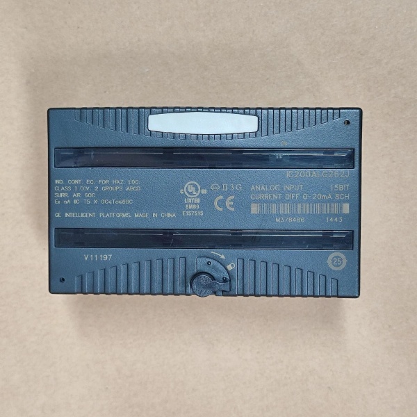
GE IC200ALG331
This module gives you a clean differential interface for 4-20mA current loops without needing external power—everything runs from the VersaMax backplane. The jumper-configurable range selection lets you switch between 4-20mA (live zero) and 0-20mA (dead zero) applications without swapping hardware, while the open-wire detection in 4-20mA mode catches broken transmitter leads before your process drifts into dangerous territory.
Where you’ll typically find it:
- Chemical process control rooms interfacing to pressure transmitters and flow meters on custody transfer loops
- Water treatment plants receiving 4-20mA signals from turbidity and pH transmitters
- VFD control panels monitoring analog speed reference feedback signals for motor synchronization
Bottom line: It’s your workhorse current loop interface that brings eight differential channels to the VersaMax rack with the diagnostics you need to trust your analog data.
Hardware Architecture & Under-the-Hood Logic
The IC200ALG262 is a single-slot VersaMax I/O module that contains an 8-channel multiplexed ADC subsystem with differential input conditioning. The module receives all operating power from the VersaMax backplane (+5V bus) and provides intelligent processing through the CPU or Network Interface Unit (NIU). All eight input channels are configured as a single group, meaning they share a common reference point.
Signal processing breakdown:
- Current loop signals enter through differential input terminals (IN+ and IN- pairs) and pass through input protection circuitry
- 100-ohm input resistors convert the incoming current to a measurable voltage drop for the ADC
- Analog multiplexer sequentially routes each channel’s conditioned signal to the 15-bit ADC
- ADC digitizes the voltage value with reference to the module’s internal precision voltage standard
- Microprocessor scales the digital count based on the configured range (4-20mA or 0-20mA):
- 4-20mA: Counts = (Current in mA – 4) × (32000 / 16)
- 0-20mA: Counts = (Current in mA) × (32000 / 20)
- Count values are rounded down to the nearest multiple of 4 for internal consistency
- Open-wire detection circuit monitors for currents below 4.077mA (in 4-20mA mode) and flags a fault
- Diagnostics check for loss of internal field power and report faults to the CPU/NIU
- Backplane communication handler updates the CPU input data table with all 8 channel values every 7.5 ms
- Green OK LED illuminates when backplane power is present, internal field power is functional, module is configured, and recognized on backplane

GE IC200ALG331
Field Service Pitfalls: What Rookies Get Wrong
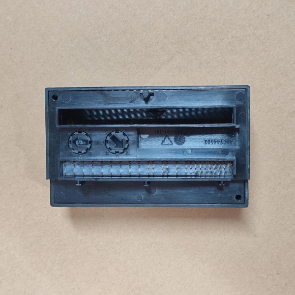
Missing the jumper for 0-20mA configurationTechs install the module and wonder why readings are offset by 4mA—the default configuration is 4-20mA (no jumper). If your transmitter puts out 0-20mA, every reading will be wrong and you’ll chase calibration ghosts.
- Field Rule: Check your transmitter output range before installing. Install the jumper on the carrier terminals for 0-20mA applications. Verify the Module ID (FFFFB408 for 0-20mA, FFFFB508 for 4-20mA) in the CPU configuration software matches your intended range.
Misunderstanding differential wiring requirementsThis module is designed for differential wiring only, but rookie engineers sometimes wire it single-ended by tying IN- to common. This kills the noise rejection and makes readings drift with ground potential differences.
- Field Rule: Always use twisted-pair shielded cable with IN+ and IN- conductors run as a pair. Ground the shield at the source device if possible—if not, ground it at the I/O module using an Auxiliary I/O Terminal (IC200TBM001/002/005). Never mix differential channels with single-ended wiring on the same module.
Ignoring common mode voltage limitsWhen you have long cable runs or installations near VFDs, common mode voltage can exceed the -10V to +10V spec. The module doesn’t outright fail, but accuracy degrades by up to 3% and you’ll see erratic readings.
- Field Rule: Measure common mode voltage at the module terminals during commissioning with a differential probe. If you’re outside ±10V, you need isolation or shorter cable runs. Keep analog conductors away from power cables—minimum 12 inches separation in conduit or use separate trays entirely.
Expecting open-wire detection in 0-20mA modeThe module only detects open wires when configured for 4-20mA. In 0-20mA mode, a broken transmitter at 0mA looks like a valid zero reading, and you won’t know until the process goes out of control.
- Field Rule: Use 4-20mA transmitters whenever possible for the diagnostic benefit. If you must use 0-20mA, implement PLC logic to detect “stuck at zero” conditions—rate-of-change alarms or low-deviation alarms that flag zero-locked signals faster than you can manually spot them.
Forgetting the shield grounding strategyGrounding the shield at both ends creates ground loops that trash your analog readings with 50/60Hz noise. But not grounding at all turns your cable into an antenna.
- Field Rule: Ground shields at the source device 99% of the time. Only ground at the I/O module when source grounding is impossible—and then use the Auxiliary I/O Terminal designed for that purpose. Never daisy-chain shields between multiple modules on the same carrier.
Please note: The listed price is for reference only and is not binding. Final pricing and terms are subject to negotiation based on current market conditions and availability.


