
Description
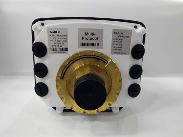
Hard-Numbers: Technical Specifications
-
Measured Gases: Hydrogen (H₂), Carbon Monoxide (CO), Methane (CH₄), Ethylene (C₂H₄), Acetylene (C₂H₂), Ethane (C₂H₆), Carbon Dioxide (CO₂)
-
Measurement Ranges: H₂: 0-2000 ppm, CO: 0-5000 ppm, Hydrocarbons: 0-1000 ppm
-
Accuracy: ±10% of reading or ±10-25 ppm (whichever is greater)
-
Moisture Measurement: 0-100% RH or 0-10,000 ppm (oil moisture content)
-
Response Time: <10 seconds (sensor level), <30 minutes for 90% step change
-
Measurement Principle: Thermal Conductivity Detection (TCD) array + electrochemical sensors
-
Communication: RS-485, Modbus RTU, Modbus TCP, Ethernet/IP, IEC 61850, DNP3.0
-
Power Supply: 100-240V AC 50/60Hz or 24V DC
-
Power Consumption: ~670mA @ +5VDC (internal)
-
Operating Temperature: -40°C to +70°C (-40°F to 158°F)
-
Storage Temperature: -55°C to +90°C
-
Enclosure: NEMA 4X (IP66) stainless steel
-
Dimensions: 482mm × 366mm × 229mm (19″ rack-mount)
or compact versions available
-
Weight: 15 kg (33 lbs) standard, 2.5 kg compact
-
Sensor Life: >10 years (field-replaceable cartridges)
-
Data Logging: Up to 1 year of data and events
-
Certifications: IEEE C57.104, IEC 60567, UL 61010-1, IEC 61850
-
HazLoc Version: M2-X-HZ certified for Class I, Division 2

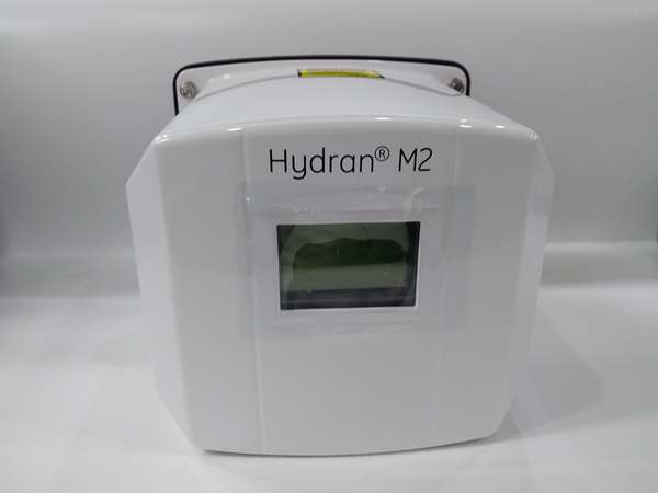
HYDRAN M2
The Real-World Problem It Solves
You know the stakes: a 500MVA transformer fails catastrophically, taking out a substation and costing $10M in replacement plus $2M/day in lost revenue. Traditional offline DGA requires oil sampling, lab analysis, and 2-week turnaround—by which time the fault has progressed from “watch” to “critical.” The HYDRAN M2 eliminates this blind spot with continuous 24/7 monitoring. It detects hydrogen (indicating partial discharge), carbon monoxide (overheated paper insulation), and acetylene (arcing) in real-time, giving you 3-6 months warning before catastrophic failure. No pumps, no moving parts, no maintenance for 10+ years—just a single valve connection to the transformer and Ethernet back to your SCADA.
Where you’ll typically find it:
-
230kV+ transformer banks in transmission substations
-
Generator step-up transformers in combined-cycle power plants
-
Offshore platform main power transformers where spares are months away
-
Data center UPS transformers where reliability is mission-critical
Bottom line: It’s an insurance policy for your most expensive assets—transforming reactive maintenance (fix after failure) into predictive maintenance (fix before failure) with data-driven confidence.
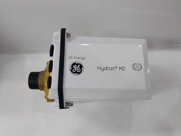
Hardware Architecture & Under-the-Hood Logic
The HYDRAN M2 is not a control system—it’s a specialized chemical analyzer. It mounts directly on the transformer tank via a single 1-inch valve (typically the drain valve or a dedicated sampling valve). Inside the NEMA 4X enclosure, a vacuum-resistant gas extraction membrane pulls dissolved gases from the oil without pumps or moving parts. The TCD sensor array measures thermal conductivity of the gas mixture, while electrochemical cells provide specific gas identification. An embedded processor runs IEEE C57.104 diagnostic algorithms to classify faults (thermal, electrical, corona) and trend gas generation rates.
Signal flow and analysis logic:
-
Gas Extraction: The permeable membrane allows dissolved gases to diffuse from oil into the sensor chamber—no oil circulation required, no pumps to fail
-
Sensor Array: Thermal Conductivity Detectors (TCD) measure overall gas concentration; electrochemical cells identify specific gases (H₂, CO, C₂H₂, etc.)
-
Signal Processing: The embedded processor applies temperature compensation and drift correction, converting raw sensor data to ppm concentrations
-
Diagnostic Algorithms: IEEE C57.104 and Duval Triangle methods classify fault types (T1-T3 thermal, D1-D2 electrical, PD partial discharge)
-
Communication: Data transmits via Modbus or IEC 61850 to SCADA/DCS; local display shows real-time trends and alarm status
-
Trend Analysis: Gas generation rates (ppm/day) are calculated and logged; sudden rate increases trigger “Alert” or “Alarm” thresholds
HYDRAN M2
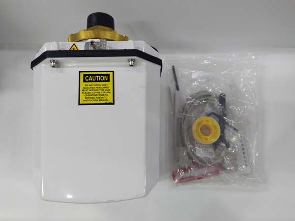
Field Service Pitfalls: What Rookies Get Wrong
Assuming It’s a Standard Analyzer Rookies treat this like a portable DGA lab unit—expecting to calibrate it monthly with span gases and zero air. It’s not. The HYDRAN M2 is factory-calibrated and uses automatic baseline correction. Attempting to “calibrate” it with bottled gases will void the warranty and likely poison the electrochemical sensors.
Field Rule: Do NOT attempt field calibration. The M2 has automatic drift compensation and self-diagnostics every 15 days
. If readings seem off, check the sensor cartridge installation date (10-year life) and verify the membrane isn’t oil-fouled. Replace the sensor cartridge as a unit—don’t try to “recalibrate” individual sensors.
Ignoring the Oil Temperature Effect Dissolved gas concentration varies exponentially with oil temperature. Rookies see a CO spike in summer and panic, not realizing the transformer is just running hotter. The M2 has a built-in temperature sensor, but rookies don’t correlate gas readings with top-oil temperature.
Quick Fix: Always check the oil temperature trend alongside gas trends. The M2 can accept external temperature inputs (top/bottom oil, ambient)
. Use the IEEE thermal models built into the firmware to calculate winding hotspot temperature and adjust gas alarm thresholds seasonally. A 20°C temperature increase can double the apparent gas concentration—don’t chase ghosts.
Installing on a Dead/De-energized Transformer The membrane extraction works by gas diffusion from oil to sensor chamber. If the transformer is offline and cold, gas solubility changes and readings drift. Rookies commission the M2 on a new transformer or after oil processing, then wonder why it shows “zero” for weeks.
Field Rule: The HYDRAN M2 requires an operating transformer (energized, loaded, oil circulating) for accurate readings. Install it during commissioning, but don’t expect meaningful data until the transformer has been loaded for at least 48 hours with oil temperature >40°C. For new transformers, baseline gas levels should be established after 30 days of operation. If the unit shows “Sensor Fault” on a cold transformer, it’s likely not a hardware problem—warm the oil first.
Forgetting the Single-Valve Installation Limits The M2 samples from one point on the tank. Rookies assume this represents the entire transformer, but gas stratification occurs in large tanks. A fault in the bottom windings may not show up in the top oil sample immediately.
Field Rule: For transformers >100MVA, consider the M2-X version with multiple sampling points or install additional Hydran units on different valves (top and bottom). The standard M2 is fine for most applications, but critical transformers may need spatial redundancy. Document the installation valve location—if the M2 shows rising acetylene but the manual lab sample from the bottom drain doesn’t correlate, you’re sampling different oil volumes.


