


Description
Hard-Numbers: Technical Specifications
- Measurement Range (Gas): 25-2000 ppm (H₂ equivalent)
- Measurement Range (Moisture): 0-100% RH
- Accuracy (Gas): ±10% of reading ±25 ppm (H₂ equivalent)
- Accuracy (Moisture): ±2% RH
- Response Time: 10 minutes (90% of step change)
- Protocol Support: Modbus RTU (Standard), DNP 3.0, IEC 61850 (Optional), Hydran Protocol
- Port Count: RS-232 (DB-9 local), RS-485 (terminal block), up to 4 analog I/O cards (optional)
- Communication Isolation: 2000 Vac RMS
- Operating Temperature (Ambient): -40°C to +55°C (-40°F to +131°F)
- Operating Temperature (Oil at Valve): -40°C to +105°C with finned heat sink adapter
- Power Supply: 90-132 Vac or 180-264 Vac, 47-63 Hz, 650VA max
- Enclosure Rating: NEMA Type 4X / IP56
- Mounting: 1.5″ NPT male thread (adapters available for 1″ or 2″ NPT valves)
- Relays: 5 dry contact relays (Form C, SPDT), 3A @ 250Vac / 3A @ 30Vdc

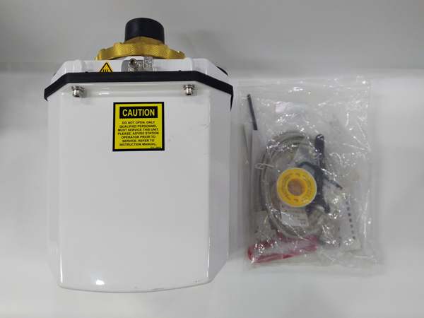
GE HYDRAN M2
The Real-World Problem It Solves
The Hydran M2 eliminates the factory-floor headache of discovering transformer insulation degradation through catastrophic failure rather than proactive intervention. By continuously monitoring dissolved fault gases and moisture levels, it shifts the maintenance strategy from reactive, calendar-based sampling to predictive, condition-based monitoring, catching thermal faults, partial discharge, and paper insulation breakdown long before they become critical failures.
Where you’ll typically find it:
- Transmission Substations: Permanently mounted on critical large power transformers where unplanned outages carry high reliability penalties and replacement costs run into millions.
- Generation Step-Up Transformers: Installed on generator step-up units in power plants (thermal, hydro, nuclear) where continuous monitoring is essential for preventing forced outages.
- Industrial Facility Transformers: Deployed on main distribution transformers in refineries, paper mills, and petrochemical plants where process interruption costs are massive and safety risks are elevated.
Bottom-line value: The Hydran M2 prevents catastrophic transformer failures by providing continuous, real-time visibility into developing insulation faults, reducing unplanned outages and extending asset life through data-driven maintenance decisions.
Hardware Architecture & Under-the-Hood Logic
The Hydran M2 operates as an intelligent monitoring node directly interfaced with the transformer oil system. The core measurement occurs through a fuel-cell type sensor positioned behind a gas-permeable membrane that is in direct contact with the transformer’s insulating oil. This membrane allows dissolved gases to pass through while blocking the oil itself, presenting the gas mixture to the electrochemical sensors. The device is not merely a passive transducer—it contains its own microprocessor that performs signal conditioning, data logging, alarm evaluation, and communication handling. The communications ports (RS-232 and RS-485) are isolated to 2000 Vac RMS, ensuring that ground potential differences or transients on the communications cabling do not damage the monitoring electronics.
Internal Signal Flow:
- Gas Extraction: Dissolved gases in the transformer oil diffuse through the gas-permeable membrane into the sensor chamber based on the concentration gradient.
- Sensor Conversion: The fuel-cell sensor generates a proportional electrical signal corresponding to the gas concentration (H₂, CO, C₂H₂, C₂H₄ depending on sensor type). The separate thin-film capacitive moisture sensor measures the water content in the oil (%RH).
- Signal Conditioning & Digitization: The analog signals from the sensors are conditioned, amplified, and converted to digital values by the onboard analog-to-digital converters.
- Microprocessor Processing: The device’s microprocessor applies calibration curves, calculates trends, compares values against alarm thresholds (Alert/Alarm levels), and optionally computes IEEE-standard transformer mathematical models (winding hot-spot temperature, moisture in paper, etc.) when additional sensor data is available.
- Data Output & Alarm Activation: Processed data is made available via local display, logged internally, and transmitted through communication protocols (Modbus, DNP3, IEC 61850). If thresholds are exceeded, the Form C relays change state to trigger local or remote alarms.
GE HYDRAN M2
Field Service Pitfalls: What Rookies Get Wrong
Improper Valve Selection and Mounting Orientation
Many technicians attempt to mount the Hydran M2 on any available oil valve without considering oil flow dynamics or valve thread compatibility. Installing the device on a stagnant oil leg or a valve where oil doesn’t freely circulate results in delayed or inaccurate gas readings because the sensor is measuring a localized pocket of oil that doesn’t represent the transformer’s overall condition. Additionally, forcing incompatible thread connections (like directly screwing a 1.5″ NPT male thread into a 1″ NPT female valve without an adapter) can damage the valve or create a leak path.
- Field Rule: Always mount the Hydran M2 on a main oil sampling valve where oil is actively circulating. Use the proper NPT adapter (1″ to 1.5″ or 2″ to 1.5″) to ensure a sealed, mechanical connection. Never install on dead-leg piping.
Ignoring the Finned Heat Sink Adapter in High-Temperature Environments
Technicians often overlook the optional finned heat sink adapter, especially in outdoor installations in hot climates or on transformers running at high oil temperatures. When the ambient temperature exceeds 40°C (104°F) or the oil temperature at the valve exceeds 90°C (194°F), the electronic compartment of the Hydran M2 can overheat. This thermal stress accelerates component aging and can lead to intermittent faults or complete failure of the electronics, resulting in a dead monitor when you need it most.
- Quick Fix: In any installation where ambient temps can exceed 40°C or oil temps exceed 90°C, always use the finned heat sink adapter. It provides passive cooling to the electronic housing, significantly extending the device’s operating life and reliability in harsh environments.
Failing to Configure Alarms Based on Transformer Specifics
A common mistake is using default alarm thresholds across all transformers without considering the unit’s specific rating, loading profile, and oil type. Generic thresholds (e.g., 200 ppm gas level) may be too sensitive for heavily loaded units or too lax for critical spare transformers. Furthermore, failing to utilize the rate-of-change (trend) alarm functionality means you’re only reacting to absolute values, missing rapidly developing faults where the rate of gas generation is the critical early indicator.
- Field Rule: Configure alarm thresholds based on the specific transformer’s IEEE C57.104 baseline data and loading history. Always enable and tune the rate-of-change alarms (hourly/daily trend) to catch developing faults early. Consult the transformer’s DGA history for proper setpoint calibration.
Commercial Availability & Pricing Note
Please note: The listed price is for reference only and is not binding. Final pricing and terms are subject to negotiation based on current market conditions and availability.


