
Description
Hard-Numbers: Technical Specifications
- Measurement Range: 0-2000 ppm (volume/volume, H₂ equivalent)
- Measurement Accuracy: ±10% of reading ±25 ppm (H₂ equivalent)
- Sensor Response Time: 10 minutes (90% of step change)
- Gas Sensitivity (Relative): H₂: 100%, CO: 15±4%, C₂H₂: 8±2%, C₂H₄: 1.5±0.5%
- Analog Output: 4-20mA for 0-2000 ppm range, 10V load max, isolated 2000V AC RMS
- Communication: USB Type B (local), RS-485 isolated 2000V AC RMS, Modbus/Hydran protocols
- Alarms: 3 dry contact relays (Type C SPDT): Gas Hi, Gas Hi-Hi, Service/Fail, 3A @250V AC, 3A @30V DC
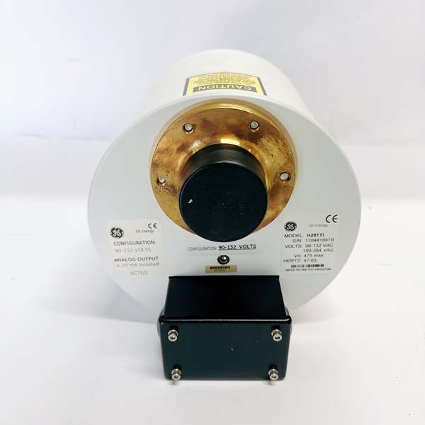
- Power Requirements: 90-132V AC or 180-264V AC switchable, 47-63Hz, 475VA maximum
- Operating Temperature (Ambient): -40°C to +55°C
- Oil Temperature Range: -40°C to +105°C (+221°F with finned heat sink adapter)
- Oil Pressure Range: 0-700 kPa (0-100 psi), vacuum-resistant sensor
- Enclosure Rating: NEMA 4X (IP66) certified
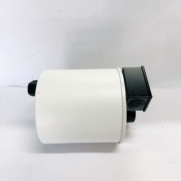
- Dimensions: 178mm diameter × 180mm length (7″ × 7-1/8″)
- Installed Weight: 5.6 kg (12 lb), Shipping Weight: 6.9 kg (15 lb)
- Display: Backlit LCD, 2 lines × 16 characters with 6-key keypad
- Mounting: Direct mount on 1″, 1.5″, or 2″ female NPT valve

GE H201Ti
The Real-World Problem It Solves
Transformers fail catastrophically when dissolved gases in oil reach dangerous levels—hydrogen indicates general faults, CO signals overheated paper insulation, acetylene means arcing, and ethylene points to overheated oil. This unit mounts directly on the transformer valve, continuously sampling oil without pumps or piping, detecting these gases in real-time and alerting operators before expensive transformer failures occur.
Where you’ll typically find it:
- Utility substations monitoring critical power transformers for predictive maintenance
- Industrial facilities with large distribution transformers in steel mills, refineries, and chemical plants
- Wind farm step-up transformers where offline oil sampling is impractical
- Less-critical transformers in the fleet where full chromatograph systems aren’t justified
Bottom line: This is the first line of defense for transformer health monitoring—no pumps, no piping, just bolt it on and get real-time fault gas data with IEEE C57.104-compliant early warning.
Hardware Architecture & Under-the-Hood Logic
The H201Ti is a self-contained DGA transmitter mounted directly on a transformer oil valve. Inside the NEMA 4X cylindrical enclosure, a fuel cell sensor with a gas-permeable membrane contacts transformer oil through a flooded manifold. Gases dissolve through the membrane and react with the fuel cell, generating electrical signals proportional to gas concentration. The microprocessor conditions these signals, compensates for temperature, calculates the composite “Hydran gas value,” and outputs data via local display, analog 4-20mA, RS-485 Modbus, and alarm relays.
- Fuel Cell Sensor Assembly: Gas-permeable membrane allows H₂, CO, C₂H₂, and C₂H₄ to pass from oil into the electrochemical cell where gases react with oxygen, producing microvolt-level signals proportional to concentration
- Temperature Control System: Thermistors in sensor body and heating plate measure temperature; time-proportioning controller maintains sensor at 25-45°C setpoint via 325W heating plate, ensuring measurement accuracy across ambient extremes
- Signal Conditioning Circuit: Microvolt signals split into two scales, amplified through analog front-end, converted to digital via ADC, processed by microprocessor with calibration compensation
- Microprocessor Core: 32-bit CPU executes real-time OS, runs sensor calibration algorithms, calculates composite gas value using relative sensitivity factors, manages data logging and self-test routines
- Memory System: Nonvolatile memory retains calibration parameters, historic data (hourly/daily trends), and configuration during power loss or battery replacement; 3V lithium/manganese dioxide battery (950mAh) provides backup
- Communication Subsystem: Isolated RS-485 transceiver (3000V opto-isolated) supports Modbus RTU and proprietary Hydran protocol for supervisory link to H201Ci controllers or remote SCADA; USB Type B for local laptop connection
- Alarm Relay Module: Three SPDT (Type C) relays with NO/NC contacts rated 3A@250V AC, 3A@30V DC: Gas Hi alarm, Gas Hi-Hi alarm, Service/Fail alarm (power loss, sensor fault, communication failure)
- Analog Output Stage: Isolated 4-20mA current loop output proportional to 0-2000 ppm gas concentration, drives up to 10V load impedance, 2000V AC RMS isolation for ground loop immunity
- Self-Test Diagnostics: Automatic 15-day self-test cycle checks battery voltage, sensor status, power supply integrity, communication health; triggers service alarm if fault detected
- Enclosure Thermal Management: 325W heating plate plus convection cooling maintains sensor and electronics within 15-65°C range; thermostat limits heating plate to 100°C maximum
The composite “Hydran gas value” represents H₂-equivalent concentration calculated as: Value = H₂ × 100% + CO × 15% + C₂H₂ × 8% + C₂H₄ × 1.5%. This single value provides a comprehensive fault indicator covering all major failure modes. Alarms can be configured on absolute ppm levels or rate-of-change (hourly/daily trends), detecting slowly developing faults through ROC monitoring. The Dynamic Oil Sampling system requires no pump—oil naturally contacts the sensor through the flooded port. Battery backup ensures data retention during power outages; estimated life is 6 years at 25°C service.
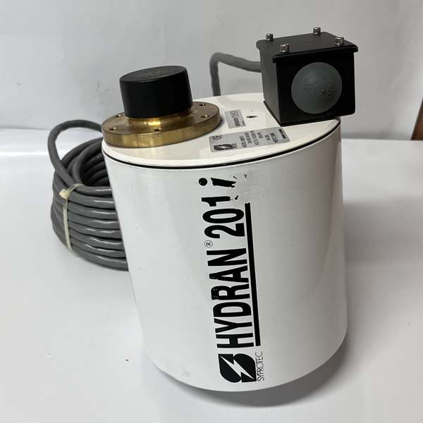
GE H201Ti
Field Service Pitfalls: What Rookies Get Wrong
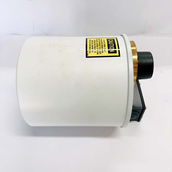
Mounting Orientation and Location ErrorsTechs install the H201Ti vertically or at an angle on the transformer valve, causing gas bubbles to collect and creating measurement errors. They also install on dead legs where oil doesn’t circulate.
Field Rule: Mount horizontally only, with the bleed screw at 12 o’clock position (top). Install on active oil circulation points—main oil valve, not sampling valve or drain. Verify oil flows freely past the sensor by opening the valve briefly during installation. If strong vibration exists, install supporting bracket. Mount height should allow oil pressure to stay within 0-700 kPa—avoid mounting at the very top or bottom of the transformer where pressure may be problematic. Document installation location with photos.
Sensor Heating Failure in Cold ClimatesIn cold environments (-40°C ambient), the 325W heating plate can’t maintain sensor temperature if oil temperature drops too low. Techs ignore the finned heat sink adapter requirement.
Field Rule: For ambient temperatures below -20°C or oil temperatures below -30°C, order the finned heat sink adapter option (1.5″ NPT). This increases heat dissipation efficiency and allows operation to -40°C ambient. Verify sensor temperature stays within 15-65°C range using internal diagnostics—check “SENSOR TEMP” display in menu. If sensor temp drops below 15°C, measurements drift. In extreme cold, consider an external enclosure heater or relocate to warmer location.
RS-485 Network Termination and GroundingJuniors daisy-chain multiple H201Ti units without proper termination, causing communication errors and data corruption. They also ground the shield at both ends, creating ground loops.
Field Rule: Install 120Ω termination resistor at both ends of the RS-485 bus only. Maximum cable length for all cables combined is 1200m. Use twisted pair cable (AWG #16 or #18) with overall shield. Ground the shield at the controller end only—leave the far end floating. Verify communication quality by monitoring error counters in the H201Ti diagnostics menu. If errors accumulate, check cable length, termination, and shield grounding. Never exceed 32 devices on one RS-485 segment.
Calibration Verification MisunderstandingTechs assume the sensor never needs calibration because it’s “fuel cell technology.” They skip annual verification against lab DGA results, leading to drift-induced false alarms or missed faults.
Field Rule: Perform annual calibration verification by comparing H201Ti readings with laboratory DGA analysis from the same oil sample taken within 24 hours. Acceptable deviation is ±10% of reading ±25 ppm. If deviation exceeds spec, perform sensor recalibration using standard calibration gas kit. Document verification results in maintenance log. Sensor life is typically 5 years under normal conditions—plan replacement proactively, not after failure.
Analog Output Loading IssuesThe 4-20mA output drives a maximum 10V load. Techs connect multiple receivers or long cable runs, exceeding load impedance and causing output saturation or erratic readings.
Field Rule: Calculate total loop resistance: R = V/I. With 10V max at 20mA, maximum load is 500Ω. If connecting multiple devices, ensure total resistance stays below 500Ω. For long cable runs, measure actual loop resistance with multimeter—use larger gauge wire if needed. Test output by injecting known gas concentrations and verifying 4-20mA corresponds correctly. Use isolated receivers to prevent ground loops that can distort the analog signal.
Oil Valve Closed Condition IgnoranceWhen transformer maintenance requires closing the oil valve, techs forget to disable the H201Ti or don’t understand how it responds to zero oil flow.
Field Rule: The H201Ti detects closed oil valve conditions and triggers a Service alarm (FAIL condition). If valve must be closed temporarily, you can disable valve monitoring in the menu or accept the alarm. For extended outages, consider powering down the unit. When reopening the valve, verify oil flow by checking pressure and purging air from the sensor using the bleed screw. Document valve closure events in maintenance records.
Battery Replacement Data LossWhen replacing the 3V lithium battery, techs disconnect power first, which erases sensor parameters and calibration data stored in volatile memory.
Field Rule: Before battery replacement, back up all configuration parameters using Hydran Host software via USB. Replace battery with power connected if possible—this preserves volatile data. If power must be disconnected, be prepared to re-enter sensor parameters from documentation. New battery wires connect to W8 (red, +) and W9 (blue, -) on the CPU module PCB. Use exact replacement type: 3V lithium/manganese dioxide, 950mAh capacity. Document battery replacement date.
Self-Test Alarm MisinterpretationThe automatic 15-day self-test triggers a Service alarm for minor issues like battery approaching end-of-life. Techs assume it’s a critical failure and shut down the monitoring system.
Field Rule: When Service alarm activates, check the alarm message display for specific cause: “BATT LOW” means replace soon but not immediate; “SENSOR FAIL” is critical. Press the alarm acknowledge button to clear and monitor the condition. For battery low, schedule replacement within 3 months. For sensor fail, immediate action required—perform sensor diagnostic or replacement. Don’t disable monitoring without understanding the fault cause.
Finned Heat Sink Adapter SelectionFor high oil temperature applications (>90°C) or high ambient (>40°C), techs don’t order the finned adapter, causing the internal thermal management to fail.
Field Rule: If oil temperature at valve exceeds 90°C or ambient temperature exceeds 40°C, the standard adapter won’t provide sufficient heat dissipation. Order the 1.5″ NPT finned high-temperature brass adapter option. This increases thermal capacity and allows oil temperature operation to +105°C. Monitor internal temperature readings—if heating plate runs continuously at max power, cooling is insufficient. Consider additional external cooling or relocation.
USB Communication Driver IssuesNewer laptops don’t have native RS-232 ports, and the USB-to-RS-232 adapters often have driver conflicts or baud rate mismatches with H201Ti.
Field Rule: For local configuration, use the USB Type B port directly on the H201Ti Mark IV—no RS-232 adapter needed. If using older units with RS-232, verify USB-RS232 adapter uses FTDI or Prolific chipset with current drivers. Set communication parameters in host software: 9600 baud, 8 data bits, 1 终止 bit, no parity (unless configured otherwise). Test communication by reading device ID and firmware version before attempting configuration changes. Always verify communication is stable before uploading configuration.
Sampling Port MisuseThe external sampling port (5/32-inch Allen screw) allows manual oil sampling with glass syringe and Luer 终止cock. Techs use it for calibration injection or open it while the unit is energized.
Field Rule: The sampling port is for manual oil extraction only—never inject calibration gas through this port. Calibration uses the factory calibration process, not field injection. When sampling oil for lab comparison, use clean glass syringe with Luer 终止cock. Take sample immediately after H201Ti reading for accurate correlation. Never open the port under pressure—oil will spray. Close securely after sampling to prevent air ingress. Document sampling events.
Commercial Availability & Pricing Note
Please note: The listed price is for reference only and is not binding. Final pricing and terms are subject to negotiation based on current market conditions and availability.


