
Description
Hard-Numbers: Technical Specifications
- Input Voltage: 24V DC
- Output Voltage: 24V DC
- Operating Temperature Range: -40°C to +85°C
- Storage Temperature Range: -40°C to +85°C
- Communication Interfaces: RS485, Ethernet
- Supported Protocols: Modbus, Profibus
- Environmental Protection: IP65 (dust-tight, water-jet protected)
- Dimensions: 10 × 10 × 10 cm
- Weight: 1 kg
- Certifications: CE, UL, ISO 9001, RoHS compliant

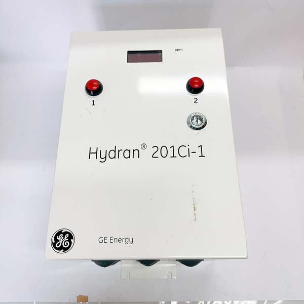
GE H201CI-1
The Real-World Problem It Solves
Industrial automation systems in harsh environments demand controllers that can survive dust, moisture, and temperature extremes while maintaining reliable communication. This module delivers IP65 protection and dual protocol support, eliminating the need for separate communication bridges and reducing failure points in dirty, wet factory floors.
Where you’ll typically find it:
- Manufacturing plants controlling assembly lines and conveyor systems
- Process industries with high humidity and dust (pulp & paper, food processing)
- Factory automation requiring robust RS485/Ethernet gateway functionality
- Robotics applications in non-ideal environmental conditions
Bottom line: This is the go-to control module when you need IP65-rated dust and water protection with built-in Modbus/Profibus flexibility in industrial automation environments.
Hardware Architecture & Under-the-Hood Logic
The H201CI-1 is a 24V DC control module designed for industrial automation with dual communication ports. The module houses the control logic processor, communication interfaces, and I/O conditioning circuitry in a sealed IP65 enclosure. The RS485 port supports Modbus RTU communication, while the Ethernet interface handles Modbus TCP and Profibus over TCP/IP protocols. The internal power conditioning accepts 24V DC input and provides regulated 24V output for field devices.
- Main Control Processor: Embedded microcontroller executing control logic, managing communication stacks for Modbus and Profibus protocols, handling I/O scanning and processing
- Power Supply Section: 24V DC input filtering, overvoltage protection, reverse polarity protection, DC-DC conversion providing regulated internal power rails
- Communication Subsystem – RS485: RS485 transceiver with galvanic isolation, supporting up to 32 nodes on the bus, automatic direction control, surge protection for industrial EMI environments
- Communication Subsystem – Ethernet: 10/100Base-T Ethernet controller with magnetic isolation, RJ45 connector, supports Modbus TCP and Profibus over TCP/IP, auto-MDIX functionality
- I/O Conditioning: Digital input filtering (debouncing), analog-to-digital conversion, output driver circuits with short-circuit protection
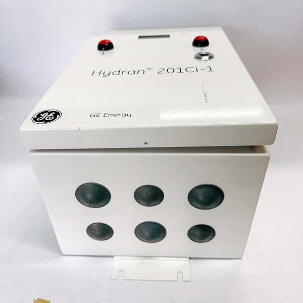
- Environmental Protection: IP65-rated enclosure sealing against dust ingress and water jets, gasketed terminal covers, sealed connectors, conformal coating on internal PCB for corrosion resistance
- Status Indication: LED indicators for power, communication status, fault conditions, module health monitoring
- Thermal Management: Passive conduction cooling through enclosure, internal temperature monitoring, thermal shutdown protection above 85°C
The module operates from a single 24V DC supply, which powers both internal electronics and provides 24V output for field devices. The dual communication architecture allows simultaneous Modbus RTU (RS485) and Modbus TCP/Profibus (Ethernet) operation, enabling bridging between legacy serial networks and modern Ethernet-based PLC/DCS systems. The IP65 enclosure ensures reliable operation in dusty, wet environments where standard industrial controllers would fail.
GE H201CI-1
Field Service Pitfalls: What Rookies Get Wrong
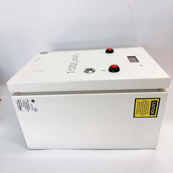
IP65 Seal DegradationTechs damage the IP65 sealing gaskets during maintenance by overtightening terminal covers or using incorrect torque specs. Once the seal is compromised, dust and moisture ingress kills the module within months.
Field Rule: Never use power tools on enclosure screws—hand-tighten only. Inspect gaskets before closing: look for cracks, compression set, or debris. Clean mating surfaces with lint-free cloth. If gasket is damaged, replace it—never reuse a compressed gasket. Torque screws to manufacturer spec (typically 1.0-1.5 Nm for M4 screws). Document any seal replacements.
RS485 Grounding and Termination ErrorsJuniors ground the shield at both ends, creating ground loops. Or they forget termination resistors on long bus runs, causing reflection errors and data corruption.
Field Rule: RS485 requires proper termination and grounding. Install 120Ω termination resistor at both ends of the bus only. Ground the cable shield at the PLC/controller end only—leave the far end floating. Use twisted pair with shield, minimum 22 AWG. For runs >1000ft, consider adding mid-point repeaters. Measure bus noise with oscilloscope—reflection spikes >0.5V indicate missing termination.
Ethernet Auto-MDIX AssumptionsTechs assume Ethernet will auto-negotiate and skip testing crossover cables. Older switches don’t support auto-MDIX, causing link failures that waste hours troubleshooting communication.
Field Rule: Always test with both straight-through and crossover cables during commissioning. If link fails, swap cables immediately. Verify switch supports auto-MDIX—check switch documentation. Use shielded Cat5e or Cat6 for industrial environments with high EMI. Test link speed with network analyzer—force 100Mbps full duplex if auto-negotiation is unstable. Document cable type and switch settings.
24V Output Current OverloadThe module provides 24V output for field devices. Techs power too many devices from this output, exceeding current capacity and causing voltage sag or thermal shutdown.
Field Rule: Calculate total load current before connecting devices. Module output typically rated 500mA-1A maximum—verify in datasheet. Measure voltage at the output terminals under full load—if it drops below 22V, you’re overloading. Distribute loads across multiple 24V supplies if needed. Use appropriate wire gauge for output conductors—18 AWG minimum for currents >200mA. Document load calculations and measured voltages.
Profibus and Modbus Address ConflictsJuniors assign the same address to multiple devices on the same network, causing communication collisions and complete bus failure.
Field Rule: Maintain a live address register document. Every device on the network must have a unique address. Scan the bus with configuration software before commissioning—duplicate addresses will appear as ghost devices. Use address ranges to segregate device types (e.g., 1-10 for PLCs, 11-30 for sensors). Never change addresses without updating documentation. Test each device individually before integrating into the network.
Temperature Stress in High-Ambient InstallationsTechs install the module in enclosures with inadequate cooling in hot environments. Internal temperature exceeds 85°C, triggering thermal shutdown and damaging components.
Field Rule: Calculate worst-case internal temperature: Tambient + (Power dissipation × thermal resistance). Measure ambient in the installed location—don’t guess. If ambient is 60°C and module dissipates 10W with 5°C/W resistance, junction hits 110°C—way over limit. Install forced ventilation or move to cooler location. Monitor module temperature during first week of operation using internal diagnostics. Document ambient temperature readings and cooling calculations.
Missing Surge Protection on Communication LinesTechs run RS485 and Ethernet cables between buildings without surge protectors. Lightning strikes or ESD events blow the communication ports instantly.
Field Rule: Install surge protectors on all communication lines entering/exiting enclosures, especially for long cable runs >50ft or between different buildings. Use ground-referenced surge protectors for RS485 and shielded surge protectors for Ethernet. Ground surge protector chassis to building ground—keep ground paths short (<3ft). Test surge protectors annually with surge generator if available. Document surge protection locations and test dates.
Conformal Coating Damage During RepairWhen opening the module for troubleshooting, techs scratch or remove conformal coating from the PCB, exposing components to moisture and corrosion.
Field Rule: Never scratch, scrape, or peel conformal coating. If rework is required, use a hot air rework station—avoid sharp tools. After repair, re-apply compatible conformal coating (same type and thickness as original). Allow full cure time before energizing. Inspect under UV light if coating contains fluorescent dye to ensure complete coverage. Document any coating repairs and materials used.
Power Supply Ripple and NoiseTechs use cheap 24V power supplies with high ripple. Noise couples into analog inputs, causing erratic readings and false alarms.
Field Rule: Measure power supply ripple with oscilloscope—should be <100mV p-p at the module terminals. Use industrial-grade power supplies with <1% ripple. Add LC filtering if needed: 100µH inductor + 1000µF capacitor close to the module. Ground all power supply returns to a single point star ground. Test with known-good industrial power supply if problems persist. Document ripple measurements and filtering solutions.
Incorrect Protocol ConfigurationTechs configure Modbus and Profibus parameters incorrectly—baud rate mismatch, parity errors, wrong slave ID. The module appears dead but is actually misconfigured.
Field Rule: Start with known-good settings: 9600 baud, 8 data bits, 1 终止 bit, no parity for Modbus RTU. Verify both ends use identical settings. Test with a single device on the network before adding more. Use protocol analyzer software to capture and decode communication frames. Check PLC/DCS side configuration matches the module settings. Document all communication parameters in the device configuration sheet.
Commercial Availability & Pricing Note
Please note: The listed price is for reference only and is not binding. Final pricing and terms are subject to negotiation based on current market conditions and availability.


