
Description
Hard-Numbers: Technical Specifications
- Input Voltage: 85-132V AC / 170-265V AC, 47-63 Hz. Selectable via internal voltage range jumper.
- Input Current: 2.0A max at 120V AC, 1.0A max at 240V AC.
- Output 1 (Logic): +5V DC, 7.0A max (35W). Shared load in redundant pair.
- Output 2 (I/O): +24V DC, 1.5A max (36W). Shared load in redundant pair.
- Total Power per Module: 71W maximum combined output. Two modules share the total rack load.
- Load Sharing Imbalance: Typically <5% between modules under normal operation.
- Transfer Time on Failure: <1 ms. Prevents PLC or I/O dropout during supply failure.
- Isolation Rating: Input to Outputs: 1500V AC RMS. Output-to-output isolation is maintained.
- Operating Temperature: 0°C to 60°C (32°F to 140°F). Derate output current above 40°C ambient.
- Efficiency: ~85% typical at full load. Heat dissipation must be managed in the rack.
- LED Indicators: OK (Green) for module healthy and online, FAIL (Red) for internal fault.
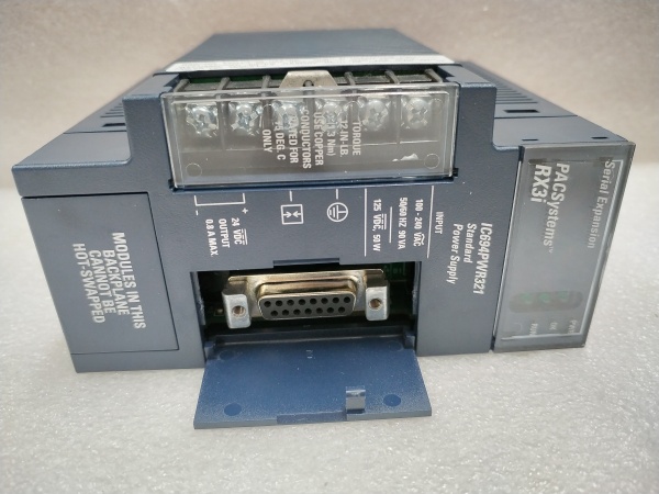
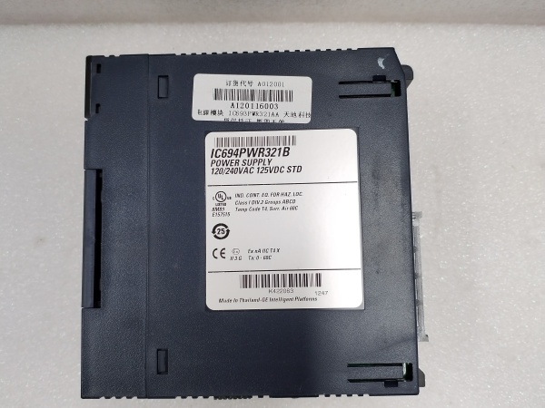
GE IC694PWR321
The Real-World Problem It Solves
A single power supply is a single point of failure. In a 24/7 operation like a packaging line or a compressor control panel, a burnt capacitor or failed rectifier in the supply shouldn’t mean a full process halt and hours of downtime. The IC694PWR331, paired with a PWR330, solves this. It stands by, sharing the load, ready to take over completely and instantly if its partner fails. This gives you the breathing room to schedule a maintenance swap during the next shift, not an emergency call at 2 AM.
Where you’ll typically find it:
- Automated Material Handling Systems: Where conveyor and sorting logic must run continuously to avoid jams and logistical chaos.
- Food & Beverage Processing PLC Cabinets: High humidity and washdown environments that stress power components.
- Critical Pumping Stations (Oil, Water): In unmanned facilities where reliability is paramount and response times are long.
It’s not about adding complexity; it’s about adding resilience. You’re buying insurance against an unplanned event that has a 100% probability of eventually happening.
Hardware Architecture & Under-the-Hood Logic
The PWR331 is not a “slave” unit. It is a peer, identical in every operational aspect to the PWR330. The redundancy is achieved through analog current-sharing and digital communication between the two peers over a dedicated cable. Each module has autonomous control but acts in concert.
- Independent Power Conversion: Each module independently converts its AC input to regulated +5V and +24V DC through full switching and isolation stages—just like a standalone supply.
- Current Share Bus Operation: The outputs of both modules are connected in parallel to the rack’s power bus. A dedicated current-share signal line (part of the redundancy cable) allows each module to compare its output current to the other’s. Their internal controllers make micro-adjustments to their output voltages to ensure they share the total load nearly equally (typically within a 5% imbalance).
- Peer-to-Peer Status Monitoring: A separate status/control line in the redundancy cable carries a digital handshake. Each module broadcasts a “I’m healthy” signal. If that signal from one module drops, the other immediately recognizes its partner has faulted.
- Failover Action: Upon detecting a partner fault, the healthy module’s controller instantly adjusts its voltage regulation loop to compensate for the lost capacity and assumes 100% of the load. This transition happens within one millisecond, which is faster than the hold-up time of the downstream PLC capacitors, preventing a glitch.
- Hot-Swap Management: The control logic manages the soft-start sequence when a new module is inserted, allowing it to smoothly ramp into the current-sharing pool without causing a bus disturbance.
GE IC694PWR321
Field Service Pitfalls: What Rookies Get Wrong
Treating PWR330 and PWR331 as Different The only difference between an IC694PWR330 and an IC694PWR331 is the factory-labeled part number for kit ordering purposes. Functionally, they are interchangeable. The rookie mistake is thinking one is a “master” and must be in a specific slot, leading to confusion during spares management.
- Field Rule: For all field service purposes—troubleshooting, replacement, load calculations—treat the PWR330 and PWR331 as identical modules. You can use any two of them to form a redundant pair. Slot placement does not matter as long as they are connected with the redundancy cable.
Sourcing Redundancy Cables from Third Parties The IC694ACC300 (1 meter) and IC694ACC301 (3 meter) redundancy cables are not just fancy jumper wires. They contain critical termination networks for the current-share and status signals. Using a generic cable or making your own will not provide proper signal impedance and can lead to unstable sharing, oscillations, or failed fault detection.
- Quick Fix: Only use the genuine GE/Emerson IC694ACC300/301 cable. It’s a controlled-impedance cable assembly. Keep a spare in the panel. Its cost is negligible compared to the risk of a false failover or undetected fault.
Neglecting Independent AC Feeders The biggest pitfall is feeding both modules from the same circuit breaker or even the same phase of your plant AC distribution. A single loose lug or tripped breaker then takes out both your “redundant” supplies.
- Field Rule: For true redundancy, power the PWR330 and PWR331 from two separate, independent AC sources (different circuit breakers, preferably different distribution panels or even different phases with proper labeling). This protects against a single AC power fault. At a minimum, use two separate breakers on the same panel.
Please note: The listed price is for reference only and is not binding. Final pricing and terms are subject to negotiation based on current market conditions and availability.


