
Description
Hard-Numbers: Technical Specifications
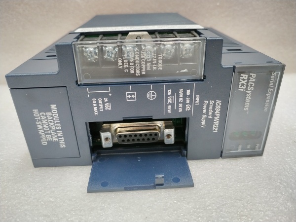
- Input Voltage: 85-132V AC / 170-265V AC, 47-63 Hz. Selectable via internal voltage range jumper.
- Input Current: 2.0A max at 120V AC, 1.0A max at 240V AC.
- Output 1 (Logic): +5V DC, 7.0A max (35W). Shared load in redundant pair.
- Output 2 (I/O): +24V DC, 1.5A max (36W). Shared load in redundant pair.
- Total Power per Module: 71W maximum combined output. Two modules share the total rack load.
- Load Sharing Imbalance: Typically <5% between modules under normal operation.
- Transfer Time on Failure: <1 ms. Prevents PLC or I/O dropout during supply failure.
- Isolation Rating: Input to Outputs: 1500V AC RMS. Output-to-output isolation is maintained.
- Operating Temperature: 0°C to 60°C (32°F to 140°F). Derate output current above 40°C ambient.
- Efficiency: ~85% typical at full load. Heat dissipation must be managed in the rack.
- LED Indicators: OK (Green) for module healthy and online, FAIL (Red) for internal fault.
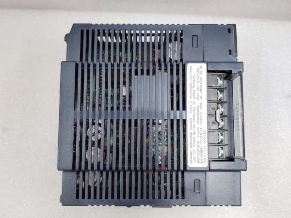
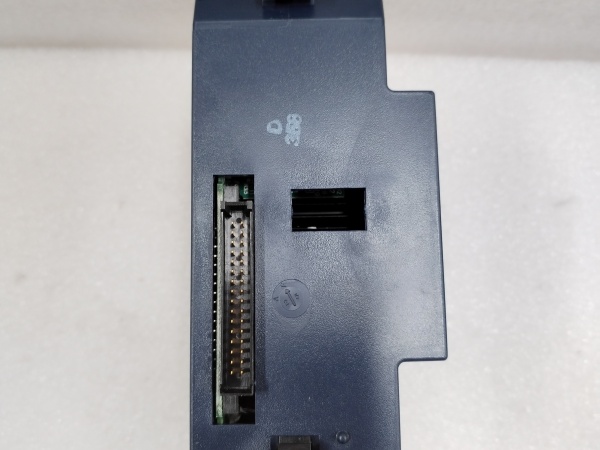
GE IC694PWR321
The Real-World Problem It Solves
You’ve got a critical process—a compressor station, a bottling line, a burner management system—where a single power supply failure cannot be the reason for a full plant trip. This module, deployed in a redundant pair, eliminates that single point of failure. If one supply dies, the other picks up 100% of the load seamlessly, giving you the window to replace the bad unit on the fly without dropping the control system.
Where you’ll typically find it:
- Continuous Process Lines (Chemical, Pharma): Where unplanned stoppages result in massive product loss or batch contamination.
- Water/Wastewater Treatment PLC Panels: Often in remote locations where immediate service isn’t available, redundancy buys time.
- Critical Machine Safety Systems: Where the PLC oversees safety interlocks, and power integrity is non-negotiable.
It’s about uptime insurance. The cost of a second power supply is trivial compared to the cost of an unexpected shutdown.
Hardware Architecture & Under-the-Hood Logic
This isn’t just a power supply; it’s an intelligent, peer-aware power node. Each module contains its own control logic for load sharing, fault detection, and hot-swap coordination. They communicate via a dedicated analog current-sharing bus and digital status lines over the special redundancy cable.
- AC Rectification & PFC: Input AC is rectified to high-voltage DC. An active Power Factor Correction (PFC) stage maintains high efficiency and minimizes harmonic feedback to the mains.
- High-Frequency Conversion & Isolation: The high-voltage DC is converted via a high-frequency switching stage and isolation transformer to create the raw low-voltage DC outputs. This stage provides the 1500V isolation barrier.
- Precision Regulation & Current Sharing: The +5V and +24V outputs are tightly regulated. A dedicated control IC monitors its own output current and adjusts its voltage setpoint slightly to achieve near-perfect load sharing with the partner module via the current-share bus.
- Fault Detection & Isolation: The module continuously self-monitors for over-temperature, over-current, and over/under-voltage faults. Upon detecting a critical internal fault, it instantly disables its outputs and signals its partner via the status line, triggering a full-load transfer.
- Hot-Swap Sequencing: When a new module is inserted into a live system, its control circuit ramps up its output voltage slowly and smoothly joins the current-sharing bus, preventing inrush and disturbance to the active power rail.
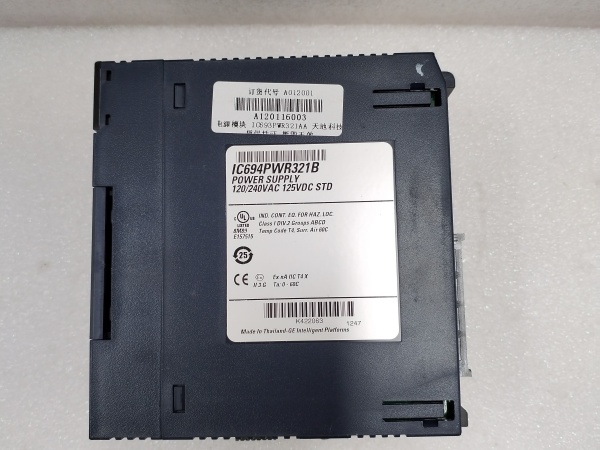
GE IC694PWR321
Field Service Pitfalls: What Rookies Get Wrong
Mismatching Modules or Using Incorrect Cables Using an IC694PWR330 with a non-redundant supply (like a PWR321) or failing to connect them with the mandatory IC694ACC300/301 redundancy cable means you have two independent supplies, not a redundant pair. They will fight each other, causing unstable voltages.
- Field Rule: Redundant pairs must be identical models (two PWR330s). They must be connected via the official redundancy cable between their communication ports. No cable, no redundancy—just trouble.
Ignoring Input Voltage Jumper Settings The module has an internal voltage range selector (120V/240V). Leaving it at the default 120V setting and connecting 240V AC will result in immediate, catastrophic failure with likely component ejection.
- Quick Fix: Before applying any power, physically remove the module and check the small jumper or DIP switch block near the input terminals. Set it correctly for your plant voltage. Document this setting on the panel door.
Assuming Redundancy Means Double the Load Capacity A common misconception is that two 71W modules give you 142W of available power. They don’t. The system is designed so that one module must be able to carry the entire rack’s load when the other fails.
- Field Rule: Your total rack load (+5V and +24V) must not exceed the maximum output of a single module (7A @5V, 1.5A @24V). Size your loads for N+1 redundancy, not N+N. Calculate your steady-state load and leave a 20% margin on a single module’s specs.
Please note: The listed price is for reference only and is not binding. Final pricing and terms are subject to negotiation based on current market conditions and availability.


