
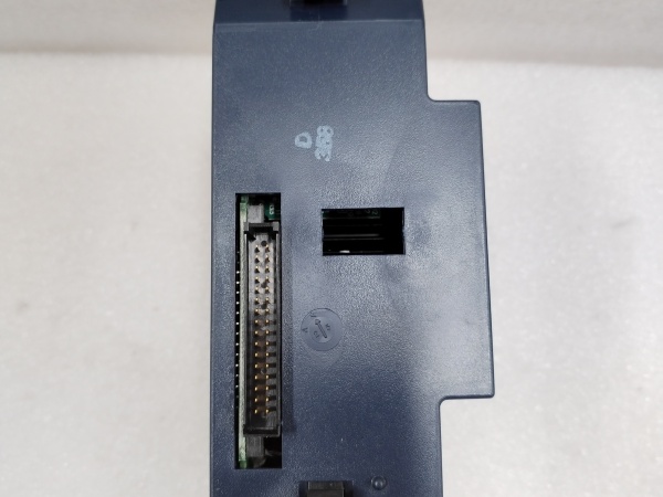
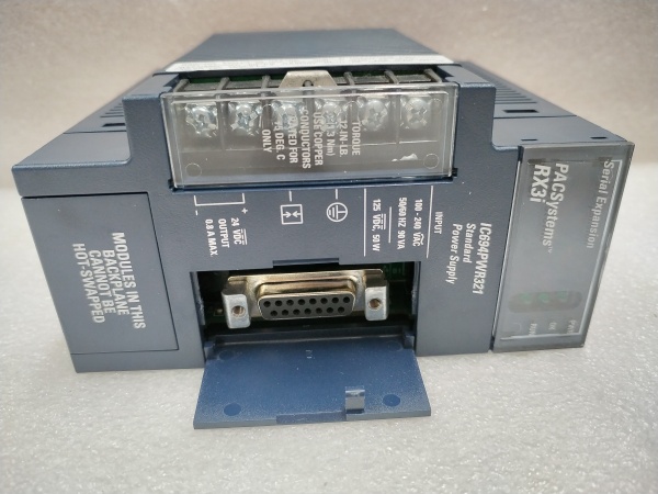
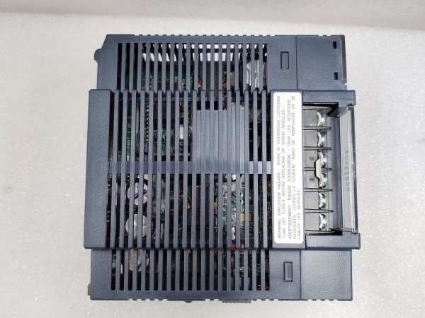
Description
Hard-Numbers: Technical Specifications
- Input Voltage: 18-32V DC. Critical range. Below 18V, the module may brown out; above 32V risks damage.
- Input Current: 3.0A maximum at 24V DC input (full load).
- Output 1 (Logic): +5V DC, 3.0A max (15W). Powers the CPU, communication modules, and backplane logic.
- Output 2 (I/O): +24V DC, 0.5A max (12W). Isolated supply for sinking/sourcing I/O points and peripheral devices.
- Total Power: 27W maximum combined output. Do not exceed.
- Isolation Rating: Input to Outputs: 1500V AC RMS. Output 1 to Output 2: Also isolated.
- Hold-up Time: Typically 20ms at nominal input, allowing for brief DC source interruptions.
- Efficiency: ~80% typical. Account for heat dissipation in enclosed racks.
- Operating Temperature: 0°C to 60°C (32°F to 140°F). Derate linearly above 40°C ambient.
- LED Indicators: PWR (Green) for input power OK, +5V (Green) and +24V (Green) for respective output status.
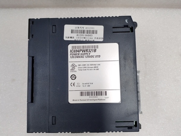
GE IC694PWR321
The Real-World Problem It Solves
You’re in a substation or on a mobile skid where only a 24V DC battery rail is available, but your 90-30 PLC needs clean, stable +5V for its brain and isolated +24V for its I/O. This module takes that noisy, fluctuating plant DC and delivers two rock-solid, isolated power rails, preventing ground loops from I/O faults from crashing the CPU.
Where you’ll typically find it:
- Battery-Backed Utility Substations: Where control logic must run from the station’s 24V DC battery bank, independent of AC mains.
- Mobile Drilling or Hydraulic Power Units: Equipment powered by vehicle or generator-based DC systems.
- Solar Farm Inverter Control Panels: Utilizing the site’s DC backbone to power the PLC for monitoring and control.
It eliminates the need for separate, bulky 5V and 24V power supplies, saving panel space and simplifying wiring, all while providing essential isolation.
Hardware Architecture & Under-the-Hood Logic
This is a dual-output, switching power supply with independent regulation and fault protection. It connects directly to the left side of the 90-30 rack, feeding the backplane. Its logic is focused on reliable conversion, isolation, and diagnostic reporting.
- Input Protection & Filtering: The incoming 24V DC passes through reverse polarity protection, EMI filtering, and inrush current limiting. This stage handles the dirty plant power.
- High-Frequency Switching Conversion: The filtered DC is chopped at high frequency by power MOSFETs, stepped down via a transformer. This provides the primary isolation and allows for compact size.
- Rectification & Regulation (Dual Rail): The transformer’s secondary windings feed two separate circuits. One is rectified and tightly regulated to +5V ±5% for logic. The other is rectified and regulated to +24V ±10% for I/O.
- Monitoring & Signaling: Each output rail has independent over-current and over-voltage protection. Monitoring circuits drive the three front-panel LEDs and can signal major faults to the CPU via the backplane.
- Backplane Interface: The module’s edge connector distributes the +5V and +24V to the backplane buses. It also draws minimal communication power for its LED status from the +5V rail it creates.
GE IC694PWR321
Field Service Pitfalls: What Rookies Get Wrong
Ignoring Total Backplane Load The rookie move is loading up every slot with modules and forgetting the math. The IC694PWR321 only has 15W for +5V logic and 12W for +24V I/O. Exceed this, and the supply current-limits, causing a brownout and erratic CPU behavior.
- Field Rule: Before installation, add up the +5V DC backplane current draw of all modules (CPU, comms, special). Then add the +24V DC load from all I/O points and sensors it’s powering. Keep totals under 3.0A and 0.5A respectively, with a 20% margin.
Miswiring the 24V DC Input Polarity The terminal block isn’t foolproof. Applying DC backwards, even briefly, can blow the internal protection diode and fry the input stage. The LED might still flicker if the diode is shorted, misleading you.
- Quick Fix: Use a meter on the incoming plant DC wires before connection. Confirm +24V DC on terminal 1 (V+) and 0V DC on terminal 2 (V-). Mark the wires. A piece of white tape with a “+” is cheaper than a new module.
Using the Isolated 24V Output as a General Supply That isolated +24V OUT (0.5A max) is for I/O circuits only. I’ve seen techs try to power a small HMI or a rack of relays with it and overload it, causing I/O to drop out.
- Field Rule: Treat the module’s 24V output as a signal power source, not a load power source. Power external devices like HMIs, radios, or heavy solenoids directly from your main plant 24V DC distribution, not from this module’s limited-capacity output.
Please note: The listed price is for reference only and is not binding. Final pricing and terms are subject to negotiation based on current market conditions and availability.


