
Description
Hard-Numbers: Technical Specifications
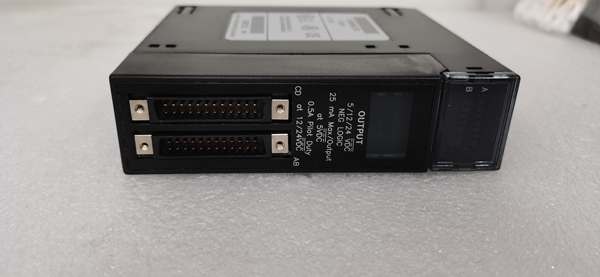
- Input Channels: 8 points in 2 isolated groups of 4
- Rated Voltage: 125VDC (positive or negative logic)
- Input Voltage Range: 0 to +150VDC
- On-State Voltage: 90 to 150VDC
- Off-State Voltage: 0 to 30VDC
- Input Current: 4.5mA typical at rated voltage
- On-State Current: 3.1mA minimum
- Off-State Current: 1.1mA maximum
- Response Time: 7ms typical (both ON and OFF)
- Isolation Rating: 250VAC continuous / 1500VAC for 1 minute (field-to-backplane, group-to-group)
- Power Draw: 40mA from 5V backplane bus + 36mA from user input supply (all inputs ON)
- Operating Temperature: 0°C to +60°C
- Humidity: 5% to 95% non-condensing
- Compatible Terminal Blocks: IC694TBB032, IC694TBB132, IC694TBS032, IC694TBS132 (ordered separately)
IC693MDL752
The Real-World Problem It Solves
You’ve got 125VDC field devices scattered across two different power distribution schemes—some sourced from a positive DC bus, others switching to DC common (negative logic). Standard input modules force you to pick one logic type for the whole card, which means separate modules for mixed-signal panels or adding isolation relays to flip polarity. This module gives you two independently configurable groups, so one card handles both sourcing and sinking devices.
Where you’ll typically find it:
- Utility substations with 125VDC control power where mixed positive/negative logic circuits exist in the same panel
- Process skids with both NPN and PNP proximity sensors on the same machine
- Legacy system retrofits where original wiring uses inconsistent polarity conventions
Bottom line: One card handles both sourcing and sinking DC inputs—cuts panel space and wiring complexity in half.
Hardware Architecture & Under-the-Hood Logic
This module uses optically isolated input channels grouped in pairs behind a common backplane interface. There’s no onboard microprocessor—signal conditioning happens in hardware, and the backplane ASIC polls the opto outputs and reports state to the CPU. Each group of 4 inputs shares a common terminal but is isolated from the other group and from the backplane logic.
- Field DC signal enters through the terminal block → each input has its own dedicated terminal with a shared common per group (4 inputs per common).
- DC signal passes through a current-limiting resistor network → drives an optocoupler LED at ~4.5mA when voltage exceeds the ON threshold (~90VDC).
- Optocoupler output switches a digital line → the backplane interface ASIC samples all 8 channels and transmits ON/OFF state to the RX3i CPU over the high-speed serial bus.
- CPU reads input state from the %I table → 7ms filter time provides noise immunity against contact bounce and transient spikes on long field cable runs.
- Logic polarity is determined by wiring, not software → positive logic inputs source current from the field device; negative logic inputs sink current to the field device’s common.
IC693MDL752
Field Service Pitfalls: What Rookies Get Wrong
Mixing Logic Types Within a Group
Each group of 4 inputs shares a common terminal. You can wire Group 1 for positive logic and Group 2 for negative logic, but you cannot mix logic types within the same group. Attempting to wire one input as sourcing and another as sinking in the same group creates a short circuit through the shared common.
Field Rule: Keep all 4 inputs in a group on the same logic type. If you need mixed logic, use both groups—or better yet, separate the devices onto different modules entirely for maintenance clarity.
Forgetting the User-Supplied Power
This module does not provide field power. The 125VDC to operate the input circuits comes from an external user supply. The module only draws 40mA from the backplane for logic operation. Forget to wire the field power supply to the common terminals, and your inputs will never turn ON regardless of field device state.
Quick Fix: Verify 125VDC is present at the common terminal for each group before commissioning. Use a meter to check voltage between the input terminal and common when the field device is actuated.
Temperature Derating on High-Density Panels
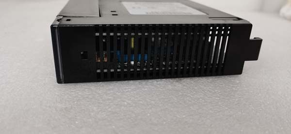
The spec sheet mentions that “maximum number of inputs on simultaneously is dependent on ambient temperature.” At 60°C ambient with all 8 inputs ON, you’re pushing the thermal limits of the optocouplers and current-limiting resistors. The module doesn’t have active cooling—just conduction through the backplane.
Field Rule: In hot panels (above 50°C ambient), derate the module. Don’t run all 8 inputs continuously ON. If your application requires sustained operation with all inputs energized, consider spacing modules apart or adding forced-air cooling. Check the manual’s derating curve—typically you lose one input per 5°C above 50°C.
Misinterpreting Negative Logic Inputs
Negative logic (sinking) inputs turn ON when the input terminal is pulled low (toward DC common). The LED on the module lights when the opto conducts—which happens when current flows from the field supply through the input device and into the module’s input terminal. Technicians often assume “ON” means “voltage present at the terminal,” but with negative logic, ON means “terminal connected to common.”
Quick Fix: When troubleshooting negative logic inputs, measure voltage between the input terminal and the field supply positive—not between input and common. A properly ON negative logic input will show near 0V to field positive, and near 125V to field common.
Commercial Availability & Pricing Note
Please note: The listed price is for reference only and is not binding. Final pricing and terms are subject to negotiation based on current market conditions and availability.


